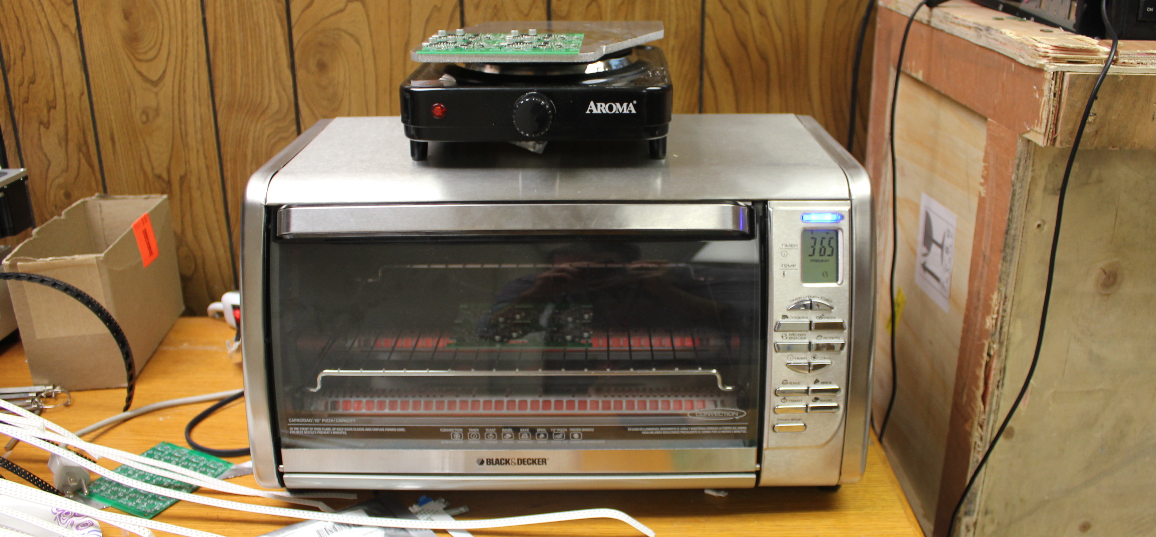
Reflow soldering sounds like something a wizard does after lunch: sprinkle silver paste, wave heat over a circuit board, and tiny components politely glue themselves into place. In real life, it is a little less magical and a lot more useful. Reflow is one of the core techniques behind modern electronics assembly, especially when working with surface-mount devices, or SMD components, that are too small, too flat, or too stubborn to solder comfortably with a traditional iron.
Whether you are building a custom keyboard, repairing a drone controller, assembling a prototype PCB, or trying to convince a QFN chip to sit still like a civilized rectangle, reflow soldering gives you a practical way to create clean, repeatable solder joints. The trick is not simply “make it hot.” The trick is using the right tools, the right solder paste, the right temperature curve, and the right amount of patience. Electronics, much like cats, can sense panic.
This guide breaks down the essential tools of the trade for reflow soldering, how the process works, where beginners go wrong, and what practical experience teaches after a few boards, a few bridges, and at least one dramatic “why is that capacitor standing upright?” moment.
What Is Reflow Soldering?
Reflow soldering is a method used to attach surface-mount electronic components to a printed circuit board. Instead of feeding solder wire into each joint one by one, you apply solder paste to the PCB pads, place components on top, and heat the board until the solder particles in the paste melt, flow, and bond the component leads or pads to the board.
The word “reflow” refers to that moment when solder changes from a dull gray paste into a shiny liquid metal connection. When done correctly, surface tension helps pull components into alignment. That tiny resistor you placed with the confidence of a caffeinated squirrel may nudge itself into a better position as the solder melts. Not every mistake is forgiven, but reflow is more forgiving than many beginners expect.
Reflow is common in professional PCB assembly because it works well for dense boards, fine-pitch integrated circuits, LEDs, sensors, and components with hidden pads. For hobbyists and small shops, it has become increasingly accessible through desktop reflow ovens, hot plates, toaster-oven conversions, hot air rework stations, and affordable solder paste stencils.
The Core Tools You Need for Reflow
1. Solder Paste
Solder paste is the star of the show. It is a mixture of tiny solder alloy particles suspended in flux. The solder forms the electrical and mechanical joint, while the flux cleans oxides from the metal surfaces and helps the solder wet the pads properly.
Common options include lead-free SAC alloys, such as SAC305, and traditional tin-lead formulas where allowed. Lead-free solder generally needs higher peak temperatures, while tin-lead paste melts at a lower temperature and can be easier for beginners. However, safety, regulations, product requirements, and personal preference all matter. If you plan to sell electronics, repair commercial equipment, or ship internationally, lead-free may be the responsible path.
Paste also comes in different particle sizes. Type 3 paste works for many general SMD jobs, while Type 4 or finer paste is better for fine-pitch components and small apertures. Store solder paste according to the manufacturer’s instructions, often refrigerated, and let it warm to room temperature before use. Cold paste can behave like grumpy toothpaste.
2. Stencils
A solder paste stencil is a thin sheet, usually stainless steel or polyimide, with openings cut to match the PCB pads. You align the stencil over the board, spread paste across it, lift the stencil, and ideally leave neat little deposits of paste exactly where they belong.
For one-off boards, you can apply paste by syringe, toothpick, or small needle tip. That works, especially for larger components. But once you deal with dozens of 0603 passives, fine-pitch ICs, or multiple boards, a stencil saves time and dramatically improves consistency. A good stencil turns “I hope this is enough paste” into “that looks almost professional, and I am prepared to be smug about it.”
3. Tweezers and Placement Tools
Fine-tip ESD-safe tweezers are essential. Surface-mount parts are tiny, lightweight, and surprisingly skilled at escaping into alternate dimensions. Curved tweezers help with visibility, straight tweezers help with placement, and vacuum pickup tools can be useful for larger ICs or repeated assembly.
Good lighting and magnification matter as much as the tweezers themselves. A magnifying lamp, microscope, or digital inspection camera can prevent hours of troubleshooting later. A misplaced 10k resistor and a misplaced 0.1 µF capacitor can look equally innocent until your circuit starts behaving like it has opinions.
4. A Heat Source
The heat source is where reflow setups differ most. Beginners often start with one of four options: a hot air rework station, hot plate, skillet, or reflow oven.
A hot air station is excellent for rework, small boards, QFN packages, and targeted soldering. It gives you control over airflow and temperature, but it also requires a steady hand. Too much airflow can send 0402 capacitors flying like popcorn.
A hot plate heats the board from below. It is simple, affordable, and effective for small batches. Because the whole board warms together, it can reduce the thermal shock that sometimes occurs with aggressive hot air. The downside is that top-side visibility and temperature precision vary by setup.
A toaster oven or desktop reflow oven gives more even heating and is better for full-board assembly. Professional reflow ovens use controlled profiles and conveyor systems, but small benchtop ovens can be excellent for prototypes. The golden rule: never use an oven for food after using it for soldering. Your pizza does not need a side of flux residue and heavy metals.
5. Thermocouples and Temperature Monitoring
Temperature control separates reflow soldering from “warming a board and hoping science claps.” A thermocouple lets you measure the actual board temperature, not just the air temperature inside an oven or the setting printed on a hot plate dial.
The temperature experienced by the PCB depends on board size, copper area, component mass, airflow, oven behavior, and where the sensor is placed. Heavy connectors and large ground planes absorb heat. Tiny boards heat quickly. A profile that works beautifully for one PCB may undercook or scorch another.
Understanding the Reflow Profile
A reflow profile is a temperature-over-time curve. It is the recipe that tells your board how to move from room temperature to molten solder and back again without damaging components, burning flux, or creating weak joints.
Preheat
During preheat, the board gradually rises in temperature. The goal is to avoid thermal shock and begin activating the flux. A controlled ramp is important because sudden heating can crack components, warp boards, or cause paste to slump.
Soak
The soak stage helps equalize temperature across the PCB. Large components, copper pours, and dense areas need time to catch up. Flux continues cleaning metal surfaces during this phase. Too little soak can lead to uneven reflow; too much can exhaust the flux before solder melts.
Reflow and Peak Temperature
The reflow stage takes the solder above its liquidus temperature, meaning the solder becomes fully molten. For many lead-free SAC pastes, the liquidus point is around 217°C, and peak temperatures may commonly land in the 235–250°C range depending on the paste, components, and assembly. Tin-lead pastes usually reflow at lower temperatures.
Peak temperature must be high enough to create reliable joints but low enough to avoid damaging components. Data sheets matter. Some sensors, connectors, displays, batteries, switches, and plastic-bodied parts dislike heat more than a snowman dislikes July.
Cooling
Cooling is not just “turn it off and wander away.” Controlled cooling helps form solid joints and reduces stress. Cooling too slowly or too quickly can contribute to defects. In a small workshop, the practical goal is to remove heat steadily without blasting the board with cold air.
Common Reflow Defects and How to Avoid Them
Tombstoning
Tombstoning happens when a tiny two-terminal component stands upright on one pad. It often occurs when one side of the component reflows before the other, pulling the part upward. Causes include uneven heating, mismatched pad sizes, poor paste deposits, or lightweight components placed slightly off-center.
Solder Bridges
Solder bridges form when excess solder connects adjacent pads or pins. Fine-pitch ICs are especially prone to bridging. Prevention starts with correct stencil aperture design, reasonable paste volume, accurate placement, and proper reflow temperature. Flux and solder wick can often fix bridges after reflow.
Cold Joints
Cold joints may look dull, grainy, or poorly wetted. They can happen when solder does not fully melt, the surface is contaminated, or the profile is too weak. Reliable solder joints generally show smooth wetting and a clean connection between pad and component termination.
Voids
Voids are trapped pockets inside solder joints, often under large thermal pads or bottom-terminated components. Some voiding is normal, but excessive voiding can affect thermal and electrical performance. Paste selection, stencil design, preheat behavior, and reflow profile all influence void formation.
Scorched Boards and Components
Too much heat for too long can discolor PCBs, damage plastic parts, degrade LEDs, or destroy sensitive ICs. Always check component moisture sensitivity, maximum reflow temperature, and recommended handling. Reflow is controlled heat, not a campfire for circuit boards.
Hot Air vs. Oven vs. Hot Plate: Which Tool Should You Choose?
For occasional repair work, a hot air rework station is hard to beat. It is compact, flexible, and ideal for removing or replacing individual chips. It also pairs well with a soldering iron for cleanup.
For small prototypes, a hot plate can be the most budget-friendly choice. It is simple, fast, and surprisingly capable. You can watch solder paste change appearance in real time, which helps beginners understand what reflow actually looks like.
For assembling full boards or small batches, a dedicated reflow oven is usually the better tool. It provides more uniform heating and can follow a repeatable temperature profile. If your projects involve multiple boards, fine-pitch packages, or recurring production, an oven quickly becomes more than a luxury. It becomes the difference between calm assembly and a desk covered in tiny parts, regret, and tweezers.
Safety Rules That Are Not Optional
Reflow soldering involves high heat, fumes, chemicals, and sometimes lead-containing materials. Work in a ventilated area, use fume extraction when possible, and keep food and drinks away from the bench. Wear eye protection when clipping leads, handling boards, or dealing with hot components.
Do not reuse soldering equipment for cooking. Do not leave ovens or hot plates unattended. Keep flammable materials away from the heating area. Let boards cool before touching them. A freshly reflowed PCB looks harmless, but it can still be hot enough to teach your fingertips a memorable lesson.
Practical Workflow for a Clean Reflow Job
Start by inspecting the PCB and verifying the bill of materials. Confirm component orientation before opening every tiny packet. Diodes, LEDs, ICs, polarized capacitors, and connectors all have opinions about direction.
Next, secure the PCB and align the stencil. Apply solder paste with a smooth pass, using enough pressure to fill the apertures without smearing paste everywhere. Lift the stencil carefully. Inspect the paste deposits under magnification. If the print is terrible, clean the board and try again. It is much easier to fix paste before parts are placed.
Place components with tweezers, starting with the smallest and lowest-profile parts, then moving to larger components. Check orientation twice. Then reflow the board using the appropriate heat source and profile for your solder paste and components.
After cooling, inspect every joint. Look for bridges, missing parts, tombstoned passives, shifted ICs, and dull or incomplete joints. Use a multimeter to check for shorts on power rails before applying power. The first power-up should be cautious. A current-limited bench supply is your friend; it is the bouncer standing between your board and electrical chaos.
Reflow Experience: Lessons From the Bench
The first thing experience teaches about reflow soldering is that preparation matters more than heroics. A beginner often imagines the dramatic moment is the heating stage, when the paste turns shiny and the board becomes “real.” That part is exciting, sure. But the success of reflow is usually decided earlier, during paste application, component placement, and profile planning. The oven gets the applause, but the stencil did half the work.
One of the most useful lessons is learning what “too much paste” looks like. At first, extra paste feels reassuring. More solder means stronger joints, right? Not exactly. Too much paste creates bridges, floating components, solder balls, and joints that look like they were decorated with metallic cake frosting. The best paste deposit is controlled and boring. In electronics assembly, boring is often beautiful.
Another lesson is that components move. Sometimes they move helpfully, snapping into alignment as solder surface tension does its tiny physics ballet. Other times they slide, rotate, or stand up like they are volunteering for a very small parade. This is why pad design, even paste volume, and gradual heating matter. If one pad gets hot before the other, small resistors and capacitors can tombstone. Once you have seen a 0402 resistor salute you vertically, you never forget it.
Hot air teaches humility faster than almost any tool. Set the airflow too high and the board becomes a miniature weather event. Tiny parts scatter, flux bubbles, and the operator suddenly develops the facial expression of someone who just sneezed on a jigsaw puzzle. Lower airflow, proper nozzle distance, and preheating make hot air much more predictable. The goal is to warm the joint, not launch a satellite.
Reflow ovens teach a different lesson: temperature settings are not the same as board temperature. A small toaster-style oven may say 240°C, but the PCB might be far cooler or hotter depending on thermal mass and airflow. A thermocouple taped to a scrap board or test PCB can reveal surprises. That is when you stop trusting the dial and start trusting measurements.
Inspection is the skill that quietly upgrades everything. Under magnification, a board tells the truth. You can see insufficient wetting, bridges, skewed chips, cracked joints, or paste that never fully reflowed. Many “mysterious firmware problems” are actually soldering problems wearing a fake mustache. Before blaming code, inspect the hardware.
Good reflow habits also change how you design PCBs. You begin to respect clear silkscreen markings, generous test points, sensible component spacing, and stencil-friendly footprints. You stop placing heat-sensitive parts next to giant copper pours unless there is a reason. You think about how a human will assemble the board, not just how tidy the layout looks on a monitor at midnight.
The best experience-based advice is simple: practice on low-stakes boards first. Build a small LED board, a sensor breakout, or a practice kit before attempting your masterpiece. Keep notes on paste type, oven settings, peak temperature, time above liquidus, and results. Reflow is repeatable when you treat it like a process. It is chaotic when you treat it like a toaster-based personality test.
Finally, do not chase perfection on the first try. Even professionals tune profiles, adjust stencil apertures, and inspect defects. Reflow soldering is a craft supported by science. Once you understand the tools, the temperature curve, and the visual clues, it becomes one of the most satisfying skills in electronics. Few things beat the moment when a freshly assembled board powers up correctly and you get to whisper, “I made that,” like a proud goblin with a multimeter.
Conclusion
Reflow soldering is one of the most valuable tools of the trade for anyone working with modern electronics. It makes surface-mount assembly faster, cleaner, and more practical than hand soldering every tiny pad individually. The essentials are straightforward: quality solder paste, accurate paste application, careful component placement, controlled heat, temperature awareness, and thorough inspection.
Beginners can start with a hot plate or hot air station, while more serious builders may benefit from a desktop reflow oven and thermocouple-based profiling. The process rewards patience and punishes shortcuts, but it is not mysterious. With practice, reflow turns intimidating SMD boards into manageable, repeatable projects. Just remember: measure the heat, respect the paste, ventilate the bench, and never bake cookies in the solder oven. That last one is not a suggestion; it is survival wisdom.
Note: This article is written for publication and synthesizes practical information from established electronics manufacturing guidance, solder paste documentation, PCB assembly tutorials, and hands-on reflow workflows. No source-link markup or citation placeholders have been added to keep the HTML clean for web publishing.