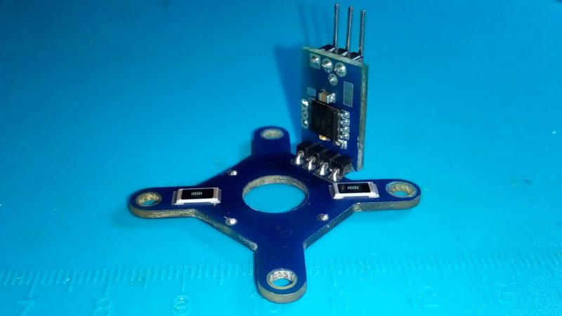
Sometimes the most delightful engineering ideas look suspiciously like someone lost a bet with a parts drawer. A quartet of SMD resistors used to sense Z-axis height sounds, at first, like a sentence that escaped from a late-night maker forum. Yet the concept is surprisingly clever: use four ordinary surface-mount resistors as strain-sensitive elements, arrange them like a tiny DIY load cell, and let a 3D printer know when the nozzle has touched the bed.
In plain English, this is a low-profile Z-axis height sensor that turns mechanical flex into an electrical signal. Instead of bolting a bulky load cell to the print head or relying on an inductive probe, the design uses four large-format SMD resistors mounted on a printed circuit board. When the nozzle contacts the build surface, the board bends slightly. That tiny deformation changes the resistance values just enough for a sensitive amplifier and analog-to-digital converter to notice. It is not magic. It is physics wearing reading glasses.
This article explains how the idea works, why it matters for 3D printer bed leveling, where it shines, where it can misbehave, and what builders should consider before treating four humble resistors like a precision measuring instrument.
What Is a Z-Axis Height Sensor?
In 3D printing, the Z axis controls the vertical distance between the nozzle and the print bed. That distance is crucial. Too high, and the first layer prints like loose spaghetti. Too low, and the nozzle scrapes the bed like it is trying to sign its name in glass. A good Z-axis sensor helps the printer detect the exact point where the nozzle, probe, or tool head reaches a known height.
Most hobby and prosumer 3D printers use one of several common probing methods: mechanical switches, BLTouch-style pins, inductive sensors, capacitive sensors, optical sensors, or load-cell systems. Each has trade-offs. Inductive sensors may struggle with glass or nonmetallic surfaces. Mechanical probes add moving parts. Offset probes measure beside the nozzle, not at the nozzle. Load-cell and strain-gauge systems are attractive because they can let the nozzle itself become the probe.
That last point is the big prize. When the nozzle is the sensor, there is no X/Y probe offset to calculate. The printer can detect the same physical point that will later extrude plastic. Fewer offsets means fewer opportunities for firmware math to wander into the weeds.
The Clever Idea: Four SMD Resistors as a DIY Strain Gauge
The featured design uses four 1 kΩ SMD resistors in the 2512 package size. The 2512 format is large by surface-mount standards, roughly 6.35 mm by 3.10 mm for many common parts, which gives the component enough physical size to participate in the mechanical flex of the board. These resistors are arranged on an X-shaped PCB so that the board can flex when the extruder or nozzle presses against the print bed.
Traditional strain gauges are specialized devices made to change resistance predictably when stretched or compressed. Ordinary SMD resistors are not sold as strain gauges, and nobody at the resistor factory is putting on a tiny lab coat and promising perfect linearity under bending loads. Still, resistors can change value when mechanically stressed. In this design, that small change becomes useful because the four resistors are wired into a Wheatstone bridge.
Why Four Resistors?
One resistor changing by a microscopic amount is easy to miss. Four resistors arranged in a bridge can turn tiny resistance changes into a measurable differential voltage. A Wheatstone bridge is a classic circuit used in load cells because it can compare resistance changes across opposing arms of the bridge. When the PCB flexes, two resistors may experience one type of strain while the other two experience the opposite. The bridge output shifts, and sensitive electronics can detect the change.
That is why the quartet matters. Four resistors do not merely sit around having a committee meeting. They work together to amplify the mechanical story the PCB is telling.
How the SMD Resistor Z-Probe Works
The mechanical structure is the heart of the idea. The PCB is shaped and mounted so that the extruder floats slightly on the board. When the nozzle touches the bed, force travels through the mount and bends the board. The resistors, placed diagonally and strategically on both sides of the board, experience strain. Their resistance shifts by a tiny amount.
That tiny electrical change is routed to a load-cell amplifier such as the HX711, a popular 24-bit ADC used for scales, force sensors, and strain-gauge projects. The HX711 is useful because bridge sensors produce very small voltage differences. A regular microcontroller analog pin would often be too noisy or too low-resolution for the job. The HX711 amplifies and digitizes the bridge output so a microcontroller can decide when contact has occurred.
In the original style of implementation, a small microcontroller such as an ATtiny85 can process the signal and pull a limit-switch input low when the trigger threshold is reached. To the printer control board, the result can look like a normal Z endstop or probe signal. Behind the curtain, however, the nozzle is quietly acting like a force-sensitive instrument.
Why This Matters for 3D Printer Bed Leveling
Automatic bed leveling is not really about making the bed level in the carpenter’s sense. It is about measuring the relationship between the nozzle and the bed across multiple points, then compensating for tilt, warp, build-surface variation, and mechanical quirks. Firmware such as Marlin and Klipper can use probing data to build a plane or mesh. During printing, the machine adjusts Z movement to keep the nozzle at a more consistent distance from the surface.
A resistor-based strain probe can be especially interesting because it detects physical nozzle contact. There is no separate probe pin to deploy. There is no inductive sensing distance that changes with bed material. There is no sideways offset between the sensor and the nozzle. The print head itself becomes the measuring tool.
For builders who enjoy compact tool heads, this matters. Conventional load cells can be too large for lightweight extruders. A PCB-based sensor using 2512 resistors can be thin, integrated, and custom-shaped for the printer. It is the kind of design that makes a maker grin and a mechanical engineer immediately ask, “What about hysteresis?” Both reactions are valid.
The Role of the Wheatstone Bridge
The Wheatstone bridge deserves a little spotlight because it is the reason this whole idea is practical. A bridge has four resistive arms. Voltage is applied across one diagonal, and the output is measured across the other. If all four resistors are balanced, the output is near zero. When strain changes the resistance values unevenly, the output moves away from zero.
In a purpose-built load cell, four matched strain gauges are bonded to a carefully designed metal beam. In the SMD resistor version, the PCB becomes the flexing beam, and the resistors become the sensing elements. It is not as refined as a commercial load cell, but it can be good enough to detect the touch event needed for Z homing and mesh probing.
Good enough is an important phrase in engineering. A 3D printer Z probe does not necessarily need to weigh a bowling ball accurately. It needs to detect bed contact repeatably, at low force, without damaging the bed, nozzle, or motion system. That is a narrower job, and this clever little circuit aims directly at it.
Advantages of Using SMD Resistors for Z-Axis Sensing
1. Compact Design
A 2512 resistor is physically large for an SMD part but tiny compared with many load cells. A PCB-based sensor can fit into a tool-head assembly where a conventional force sensor would be awkward.
2. Low Cost
SMD resistors are inexpensive and easy to source. Even when paired with an HX711 module, a small microcontroller, and a custom PCB, the total parts cost can remain friendly to experimenters.
3. No Probe Offset
Because the nozzle itself can trigger the measurement, there is no separate probe tip located beside the nozzle. This reduces calibration complexity and can improve practical accuracy during bed meshing.
4. Fewer Moving Parts
Unlike deployable probes, a strain-based nozzle sensor does not need a pin, servo, solenoid, or mechanical arm. Fewer moving parts generally means fewer tiny mechanical dramas.
5. Maker-Friendly Experimentation
The project is approachable for people who can design or order a PCB, solder large SMD parts, and tune firmware. It is a wonderful example of stretching common components beyond their normal job description without needing exotic hardware.
Limitations and Challenges
This design is clever, but it is not a free lunch. It is more like a lunch you assembled from leftovers that somehow became gourmet, provided you measure the salt carefully.
Signal Noise
The resistance changes are very small. Electrical noise, poor grounding, long wires, unstable power, and mechanical vibration can all confuse the reading. Keeping the amplifier close to the sensing bridge and using thoughtful wiring can help.
Temperature Drift
Resistors change value with temperature. 3D printers are warm machines, especially near a hotend and heated bed. Temperature changes may shift the baseline reading, so tare routines, firmware filtering, and warm-up consistency become important.
Mechanical Repeatability
The PCB must flex predictably. Mounting screws, plastic brackets, cable strain, hotend weight, belt tension, and even fan ducts can influence how force travels through the assembly. A beautiful circuit on a poorly constrained mount may still produce messy results.
Calibration Effort
A strain-based probe needs threshold tuning. Too sensitive, and it triggers from vibration. Not sensitive enough, and the nozzle presses too hard before the printer notices. The sweet spot is where the system detects contact consistently without bruising the print surface.
Practical Build Considerations
If you are inspired to build a Z-axis height sensor from four SMD resistors, start with the mechanical design rather than the code. The PCB shape, mounting points, and resistor placement determine whether the sensor sees clean strain or random mechanical gossip.
Use large SMD resistors such as 2512 packages because their size makes them easier to solder and more mechanically engaged with the board. Choose resistors with similar values and tolerances so the bridge starts reasonably balanced. The classic 1 kΩ value is convenient because it is common and works well with many bridge-reading circuits.
Place the analog front end close to the bridge. A small board carrying the HX711 and microcontroller directly on or near the sensor can reduce wire length and noise pickup. Keep high-current hotend, fan, and stepper wiring away from sensitive bridge traces when possible. The sensor signal is tiny; stepper motor noise is not tiny. It arrives wearing boots.
Mechanically, let the board flex only where you intend it to flex. Do not clamp the sensing arms so tightly that nothing moves. Do not leave the hotend wobbling like a shopping cart wheel. The design needs controlled compliance, which is the engineering way of saying, “Yes, it should bend, but only in the polite direction.”
Firmware and Calibration Tips
On the firmware side, the resistor bridge can be treated like a Z probe or endstop once the electronics convert force into a clean trigger signal. Marlin users typically think in terms of probe configuration, Z offset, and bed leveling methods such as bilinear or unified bed leveling. Klipper users may focus on probe calibration, repeatability checks, load-cell diagnostics, and bed mesh calibration.
The most important habit is repeatability testing. Probe the same spot multiple times and watch whether the trigger height remains consistent. If values drift, inspect temperature, wiring, mechanical looseness, cable tugging, and threshold settings. Many mysterious probe problems are not firmware problems at all. They are mechanical gremlins with excellent camouflage.
Warm the machine before final calibration if you normally print with a hot bed and hot nozzle. Thermal expansion affects printer geometry, and temperature can affect sensor readings. Calibrating cold and printing hot may work, but it can also lead to first-layer confusion that sends you back to the paper method while muttering at midnight.
Specific Example: How Contact Becomes a Z Trigger
Imagine a CoreXY printer with a compact direct-drive extruder. The nozzle moves to the center of the bed and slowly lowers. At first, the PCB sensor is relaxed. The Wheatstone bridge output sits near its baseline. As the nozzle touches the bed, the hotend mount transfers a small upward force into the X-shaped PCB. The PCB flexes. Two resistors experience slightly different strain than the other two. The bridge output changes. The HX711 digitizes the shift. The microcontroller compares the reading to a threshold. When the threshold is crossed, it signals the printer controller: “Stop. Contact detected.”
That single event can be used for homing. Repeat it across a grid, and the printer can map bed height. The result is a first layer that is more consistent across the build surface, assuming the sensor is stable and the machine is mechanically sound.
Where This Idea Fits Among Other Z-Probe Technologies
The SMD resistor strain probe sits somewhere between a formal load-cell system and a clever hacker shortcut. Compared with BLTouch-style probes, it can avoid deployable hardware and probe offset. Compared with inductive probes, it can work through direct contact rather than material-dependent sensing. Compared with a commercial load cell, it may be cheaper and easier to integrate into a thin tool head, but less predictable and less thoroughly characterized.
For a production printer, a validated load-cell module or professionally designed strain-gauge system may be the safer route. For an experimental printer, retrofit project, or educational build, the resistor approach is fascinating. It teaches electronics, mechanics, signal conditioning, firmware integration, and humility. Especially humility.
Common Mistakes to Avoid
Using Random Mounting Geometry
The sensor depends on controlled flex. If the board is mounted in a way that prevents bending, the signal will be weak. If it bends unpredictably, the signal will be noisy.
Ignoring Cable Strain
Cables tugging on the tool head can create false readings. Secure wires so they do not pull on the sensing structure during motion.
Skipping Shielding and Grounding Basics
Bridge signals are small. Keep analog paths short, use stable power, and route noisy wiring away from the sensing circuit.
Expecting Laboratory Accuracy
This is a practical contact sensor, not a certified metrology instrument. Judge it by repeatable Z triggering, not by whether it can weigh a raisin with philosophical certainty.
Experience Notes: What It Feels Like to Work With a Resistor-Based Z Probe
Working with a quartet of SMD resistors used to sense Z-axis height feels like building a musical instrument out of spare electronics. The concept is simple, but the tuning matters. On paper, the bridge output changes when the board flexes. In real life, your first readings may look like the sensor drank too much coffee. That does not mean the idea is bad. It usually means the build needs calmer wiring, better mounting, cleaner grounding, or a more sensible trigger threshold.
The first practical lesson is that mechanics dominate the experience. Many builders begin by staring at ADC values, but the bigger issue is often how the hotend is supported. If the nozzle can rock, twist, or drag the cable harness into the reading, the electronics will faithfully report chaos. A stable mount with a predictable flex zone makes the numbers far more meaningful. The sensor should respond strongly to vertical nozzle contact and weakly to ordinary travel vibration.
The second lesson is that calibration should be treated as a routine, not a one-time ceremony. Run repeatability tests after assembly, after tightening screws, after changing hotends, and after moving cables. A tiny mechanical change can alter the baseline. The good news is that once the structure is stable, contact-trigger probing can become pleasantly consistent. Watching the nozzle gently touch the bed and trigger without a separate probe arm is deeply satisfying, in the same way a perfectly timed toaster pop is satisfying but with more firmware.
The third lesson is to respect temperature. A cold printer on the bench is not the same machine as a printer with a heated bed, a hot nozzle, and warm air moving around the tool head. Let the printer reach normal operating conditions before final Z-offset tuning. This reduces the chance of a first layer that looked perfect during testing and then turned into transparent pancake art during an actual print.
The fourth lesson is that the resistor probe rewards patient troubleshooting. If the trigger is inconsistent, do not immediately rewrite the firmware. First, check screw tension, board flex, solder joints, connector quality, and whether the amplifier is mounted too far from the bridge. Look for fan wires, heater wires, or stepper cables crossing sensitive analog traces. Make one change at a time. Engineers call this controlled experimentation. Everyone else calls it “not creating five new problems while solving one.”
The final experience is appreciation. This design reminds us that innovation is often less about expensive parts and more about noticing hidden behavior in ordinary components. An SMD resistor is supposed to resist current. Under the right conditions, it can also help a machine feel touch. That is the fun of maker engineering: the parts bin is full of tiny actors waiting for better roles.
Conclusion
A quartet of SMD resistors used to sense Z-axis height is a brilliant example of practical creativity. By arranging four large surface-mount resistors into a bridge on a flexing PCB, a 3D printer can detect nozzle contact without a bulky load cell or offset probe. The approach is compact, inexpensive, and intellectually delicious.
It also demands respect. Small signals need clean electronics. Flex-based sensing needs careful mechanics. Temperature, cable strain, and calibration can all influence results. But when the design is built and tuned well, it offers a compelling path toward nozzle-based Z probing and automatic bed leveling.
This is not just a story about resistors. It is a story about looking at common components and asking, “What else can you do?” In this case, four tiny parts answer by helping a printer find the bed. Not bad for components usually asked to do nothing more glamorous than sit quietly and limit current.
SEO Tags
Note: This article is written for educational and informational purposes. Builders working with printer electronics should verify wiring, firmware settings, grounding, and mechanical safety before testing any custom Z-probe system on a live machine.