If you have ever stared at a tiny resistor and thought, “Cool, but who are you and why are you wearing stripes?” welcome to the club. Resistors look simple, but identifying them correctly matters a lot. Pick the wrong one, and your LED glows like a candle in a windstorm, your sensor reads nonsense, or your project produces that famous electronics smell known as “I have made a mistake.”
The good news is that resistor identification is learnable, practical, and far less mysterious than it first appears. Once you understand color bands, printed markings, package sizes, and a few multimeter tricks, you can quickly tell whether a resistor is 220 ohms, 4.7k ohms, 1M ohm, or a tiny surface-mount troublemaker pretending to be all of the above.
In this guide, you will learn how to identify resistors by appearance, decode through-hole color bands, read SMD resistor markings, estimate power rating from size, and verify everything with a multimeter. Think of it as resistor detective school, but with fewer trench coats and more magnification.
What a Resistor Usually Looks Like
Before you decode anything, it helps to know what kind of resistor you are holding. In everyday electronics, you will usually run into two broad styles: through-hole resistors and surface-mount resistors.
Through-Hole Resistors
These are the classic cylindrical resistors with a wire lead coming out of each end. They are common in hobby kits, breadboards, repair work, and older electronics. Many of them use color bands to show resistance value, tolerance, and sometimes temperature coefficient.
Surface-Mount Resistors
These are tiny rectangular parts soldered directly to the board. Instead of colored bands, they often use printed numeric or alphanumeric codes. Some are so small they have no readable marking at all, which is the electronics equivalent of getting a nameless mystery guest at dinner.
Large Power Resistors
Bigger resistors often have their value printed directly on the body. If a resistor is large enough to make room for text, manufacturers usually skip the rainbow armband routine and just print the resistance, tolerance, or part number instead.
Step One: Identify the Reading Style
The first real task is figuring out how the resistor is marked.
- If it has colored rings around the body, use the color code system.
- If it has numbers like 472, 1001, or 4R7, use the SMD marking system.
- If it has full text printed on it, read the print and confirm with a meter if needed.
- If it has no visible code at all, you may need the board schematic, bill of materials, or a multimeter.
This sounds obvious, but many identification mistakes happen because people try to read an SMD code like a color code or read a faded tolerance band backward. Resistors are humble, but they are not above causing chaos.
How to Read Through-Hole Resistor Color Bands
Color-banded resistors are the most common starting point for beginners. Once you know the logic, they become much easier to read.
Start from the Correct End
A resistor is not meant to be read from whichever side is emotionally convenient. Look for the band that is closest to one end of the resistor body. Also look for a slightly wider gap before the tolerance band. In many cases, the tolerance band is gold, silver, or brown and sits a little apart from the value bands.
If one side has a band near the edge and the other side has a band separated by more space, start from the edge-side band and read toward the isolated band. That simple habit prevents about half of all “Why is this 10 ohms becoming 1 gigaohm?” moments.
The Color Values
Here is the basic digit sequence you need to know:
Black = 0, Brown = 1, Red = 2, Orange = 3, Yellow = 4, Green = 5, Blue = 6, Violet = 7, Gray = 8, White = 9
Then come the special multiplier and tolerance helpers:
- Gold can mean a multiplier of 0.1 and often a tolerance of ±5%
- Silver can mean a multiplier of 0.01 and often a tolerance of ±10%
- No tolerance band often means ±20%
How 4-Band Resistors Work
A 4-band resistor uses:
- First digit
- Second digit
- Multiplier
- Tolerance
Example: Brown, black, red, gold
Brown = 1, black = 0, so the first two digits are 10. Red means multiply by 100. That gives you 1,000 ohms, or 1kΩ. Gold means the tolerance is ±5%.
Example: Yellow, violet, red, gold
Yellow = 4, violet = 7, red multiplier = 100. That makes 4,700 ohms, or 4.7kΩ, with a tolerance of ±5%.
How 5-Band Resistors Work
A 5-band resistor usually means more precision. It uses:
- First digit
- Second digit
- Third digit
- Multiplier
- Tolerance
Example: Brown, black, black, red, brown
The first three digits are 1, 0, 0. Red is a multiplier of 100. That makes 10,000 ohms, or 10kΩ. Brown tolerance means ±1%.
Five-band parts are common when tighter accuracy matters. If the resistor looks like it takes its job very seriously, five bands are often the reason.
How 6-Band Resistors Work
A 6-band resistor is basically a 5-band resistor with one extra band for temperature coefficient, often written in ppm/°C. That tells you how much the resistance changes as temperature changes.
For many basic hobby projects, you do not need to obsess over this sixth band. For precision circuits, industrial controls, or measurement equipment, it matters much more.
What About 3-Band Resistors?
Three-band resistors still exist, especially in older or simpler applications. They typically use two significant digits and a multiplier, with an implied tolerance of ±20%. They are less precise and easier to misread, so double-check them before trusting them with anything important.
How to Read Surface-Mount Resistor Codes
SMD resistors trade colored bands for compact printed codes. They are efficient, tiny, and not always interested in helping your eyesight.
Three-Digit Codes
In a 3-digit code, the first two digits are significant figures and the third digit is the number of zeros.
Example: 472
The first two digits are 47. The third digit means add two zeros. Result: 4,700 ohms, or 4.7kΩ.
Example: 103
The first two digits are 10. Add three zeros. Result: 10,000 ohms, or 10kΩ.
Four-Digit Codes
In a 4-digit code, the first three digits are significant figures and the fourth digit is the multiplier.
Example: 1001
The first three digits are 100. The final digit means add one zero. Result: 1,000 ohms, or 1kΩ.
Example: 4992
The first three digits are 499. Add two zeros. Result: 49,900 ohms, or 49.9kΩ.
The Letter R as a Decimal Point
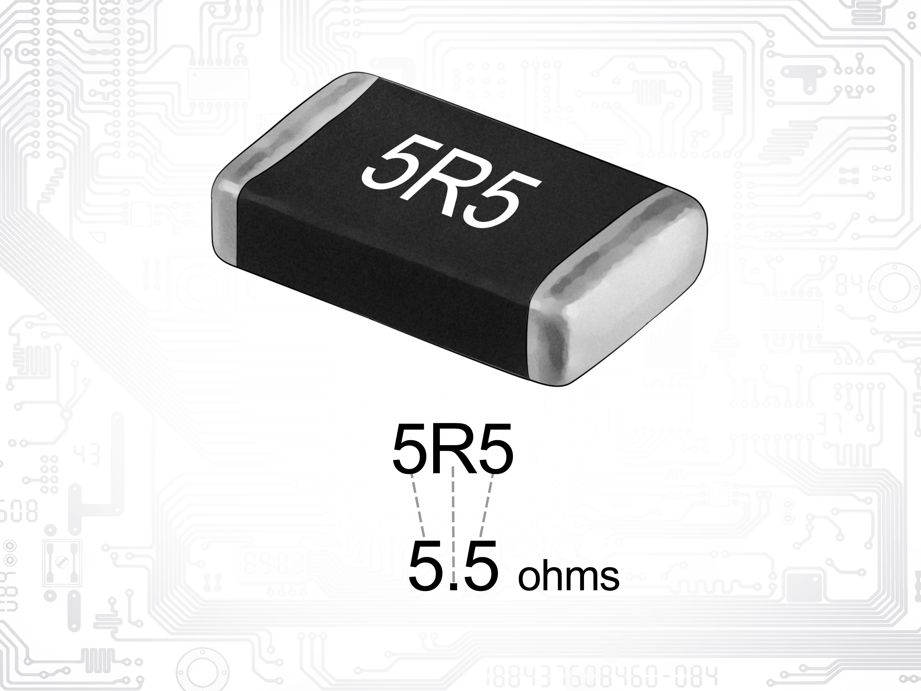
On many SMD resistors, the letter R works as a decimal point.
- 4R7 = 4.7Ω
- R47 = 0.47Ω
- 0R0 = 0Ω jumper
This is especially common in low-resistance parts where writing a normal decimal point would be too tiny to survive real life.
EIA-96 Codes
Some precision SMD resistors use an EIA-96 system, often found on 1% parts. These markings usually combine two numbers and one letter. The numbers correspond to a value from a standard table, and the letter indicates the multiplier.
In plain English: EIA-96 is efficient, accurate, and not something most humans decode from memory while standing at a workbench with cold coffee. When you see this format, use a chart or calculator.
When There Is No Marking at All
Very small chip resistors, including some 0201 and 0402 packages, may have no visible marking. Zero-ohm jumpers in very small packages may also be unmarked. In that case, your best tools are:
- the board schematic
- a bill of materials
- a known-good matching board
- a multimeter, used carefully
Use a Multimeter to Confirm the Value
If the markings are faded, suspicious, or look like they were painted on during an earthquake, use a digital multimeter.
Best Practice for Measuring Resistance
- Turn the power off.
- Discharge capacitors if the circuit contains them.
- Set the multimeter to ohms (Ω).
- Touch one probe to each end of the resistor.
- Read the value and compare it to the expected code.
If the resistor is still in the circuit, the reading can be thrown off by parallel paths through other components. For the most accurate result, remove the resistor or lift one lead from the board. In-circuit resistance measurement is helpful, but sometimes the rest of the board decides to join the conversation.
When Meter Readings Look Wrong
Common causes include:
- measuring in-circuit
- touching metal probe ends with your fingers
- poor probe contact
- a damaged resistor that has drifted out of spec
- using too low a range on the meter
A quick re-measure with one lead lifted often solves the mystery.
Can You Identify Wattage by Size?
Sometimes, yes. Always, no.
For many through-hole resistors, larger body size roughly suggests a higher power rating. A typical 1/2 watt resistor is usually larger than a 1/4 watt resistor. That makes size a useful clue. But it is not a legally binding promise from the resistor. Different materials, manufacturers, and series can produce different physical sizes for the same power rating.
So here is the smart rule: use size as a hint, not as proof. If wattage matters for a repair or a design, verify it with documentation, a schematic, a part number, or the original bill of materials.
For SMD resistors, package size codes such as 0402, 0603, 0805, and 1206 often correlate with typical power ratings, but not universally. A bigger package usually handles more power, but specialty parts can break that expectation.
Other Clues That Help Identify a Resistor
Look at the PCB Label
On a circuit board, resistors are usually labeled with a designator like R1, R12, or R205. That does not tell you the resistance by itself, but it confirms the component type and helps you look it up in the schematic.
Check the Circuit Context
A resistor next to an LED might be a current-limiting resistor. A resistor in a voltage divider might have a matching partner nearby. Current-sense resistors are often very low value and may use special printed markings. Context will not replace measurement, but it can help you rule out absurd guesses.
Watch for Damage
Burn marks, cracked coating, bubbling, or a resistor body that looks toasted are all signs that the marking may no longer be trustworthy. If the resistor looks like it survived a dramatic exit scene, measure it carefully and compare it with the schematic if possible.
Common Mistakes When Identifying Resistors
- Reading the bands backward. This is the classic mistake.
- Confusing red, brown, and orange under poor lighting. Use a bright light or magnifier.
- Assuming every SMD code uses the same system. Some use 3 digits, some 4, some EIA-96.
- Trusting an in-circuit meter reading too much. Parallel components can fool you.
- Using body size as the final answer for wattage. It is only a clue.
- Ignoring tolerance. A 10k resistor with ±5% is not the same as a 10k resistor with ±1% in every circuit.
Quick Real-World Examples
Example 1: A Common Breadboard Resistor
You find a resistor with bands brown, black, orange, gold. That is 10 × 1,000 = 10kΩ ±5%.
Example 2: A Precision Through-Hole Part
You see red, red, black, black, brown. That reads 220 × 1 = 220Ω ±1%.
Example 3: A Tiny Chip on a Modern PCB
The part says 331. That means 33 with one zero: 330Ω.
Example 4: A Low-Ohm Chip Resistor
The part says 4R7. The R is the decimal point, so the value is 4.7Ω.
Hands-On Experience: What You Learn After Identifying a Lot of Resistors
The funny thing about resistor identification is that it starts as a memorization exercise and turns into a pattern-recognition skill. The first few times you decode one, you feel like you are translating ancient cave art. After a while, you begin spotting 10k, 1k, and 4.7k values almost instantly. Brown-black-orange? Your brain starts saying “10k” before you even finish your coffee. Yellow-violet-red? “4.7k,” and now you feel slightly more powerful than you did ten seconds earlier.
In real bench work, the biggest lesson is that appearance and certainty are not the same thing. A resistor may look obvious, but faded paint, weird lighting, or heat damage can turn a simple ID job into a guessing contest. Experience teaches you to slow down and verify. You stop trusting your eyes alone and start combining clues: code, package, circuit location, and meter reading. That shift from guessing to confirming is what separates a smooth repair from a long afternoon spent asking why the replacement part is “technically correct” and yet still completely wrong.
Another thing experience teaches is that context matters more than beginners expect. If a resistor sits in series with an LED, you start expecting a modest value. If it sits near a microcontroller input, a pull-up or pull-down value like 10k becomes likely. If it is a chunky low-ohm SMD part near a power stage, you start thinking current sense resistor, not random mystery rectangle. You are not just reading markings anymore; you are reading the circuit’s habits.
You also learn humility. Everyone reads one backward eventually. Everyone mistakes brown for red under terrible workshop lighting. Everyone, at least once, measures a resistor in-circuit, gets a bizarre number, and briefly suspects the laws of physics have changed. Then you lift one lead, measure again, and remember that parallel paths are sneaky little goblins.
There is also a practical satisfaction in becoming fast at this skill. When you can sort a pile of mixed resistors without panic, build a prototype without stopping every two minutes, or repair a board without replacing the wrong part three times in a row, you feel the difference. Resistor identification is not glamorous. No one throws a parade because you correctly decoded a 5-band 0.1% part. But it is one of those foundational skills that makes every electronics task easier. It saves time, prevents errors, and builds confidence.
Most importantly, repeated experience teaches you a healthy rule: when the markings are clear, read them; when they are not, measure them; and when the result still seems weird, trust the schematic over your ego. That rule will spare you a lot of frustration and at least a few singed components.
Final Thoughts
Learning how to identify resistors is one of those small skills that pays off everywhere in electronics. Once you understand color bands, SMD number systems, wattage clues, and multimeter verification, resistors stop looking like random tiny beans and start looking like readable parts with a clear job.
The fast version is simple: identify the resistor type, read the code in the correct direction, decode the value, check tolerance, use size only as a clue for power, and verify with a multimeter when the stakes are higher than “I hope this works.” Follow that routine and you will spend less time guessing and more time building, fixing, and enjoying your projects.