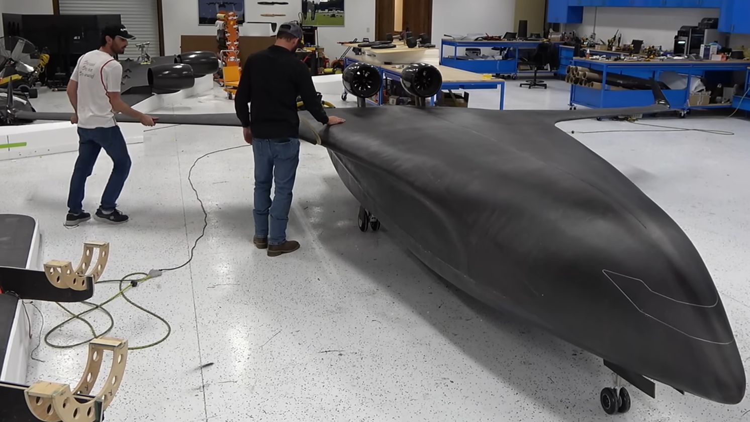
A blended wing body aircraft looks like the result of a conventional airplane melting slightly in the sunin a good way. Instead of attaching a cylindrical fuselage to two separate wings, the design smoothly merges the center body and outer wing into one lifting shape. The result can offer excellent aerodynamic efficiency, generous internal volume, and a futuristic silhouette that makes ordinary model airplanes look as though they arrived wearing office clothes.
Building a flying blended wing body aircraft prototype, however, requires more than tracing a stealth bomber onto foam board and adding a motor. Tailless aircraft can be sensitive to center-of-gravity placement, control-surface setup, structural flexibility, and low-speed handling. A successful prototype must balance aerodynamic efficiency with predictable stability, practical construction, reliable electronics, and a disciplined flight-test plan.
This guide explains how to move from an ambitious sketch to a controllable electric prototype without treating the first launch as an aerospace-themed coin toss.
What Makes a Blended Wing Body Aircraft Different?
A blended wing body, commonly abbreviated as BWB, combines the lifting function of the wing with a broad central body. Unlike a conventional tube-and-wing aircraft, much of the center section contributes useful lift. This can reduce wetted area and interference drag while creating a large internal space for batteries, cargo, sensors, or future propulsion systems.
A BWB is related to a flying wing, but the terms are not always interchangeable. A pure flying wing may have little or no distinct central fuselage. A blended wing body usually has a thicker, more voluminous center section that transitions gradually into the outer wings.
NASA and Boeing explored this configuration through the remotely piloted X-48 research aircraft. Those programs demonstrated that a subscale blended-wing vehicle could be flown and tested systematically, including investigations of low-speed handling, stall behavior, propulsion integration, noise, and flight-control logic.
The configuration also introduces several challenges:
- There is no conventional horizontal tail to provide a long pitch-control moment arm.
- Yaw stability may be weak without winglets, fins, split drag rudders, or active control.
- The center of gravity must remain within a comparatively narrow usable range.
- Control surfaces often perform multiple jobs at once.
- A thick center body may create complex airflow where it blends into the wing.
- Small prototypes operate at lower Reynolds numbers than full-size aircraft, so their airflow does not scale perfectly.
Begin With a Clear Prototype Mission
Before opening CAD software, decide what the aircraft must demonstrate. “Looking awesome” is a perfectly respectable secondary objective, but it is not a complete engineering requirement.
A first blended wing body prototype should usually have a modest mission:
- Take off or hand-launch reliably.
- Maintain stable, controllable flight.
- Demonstrate acceptable pitch, roll, and yaw behavior.
- Carry basic telemetry equipment.
- Land without converting itself into modern art.
A practical first prototype might use an electric pusher motor, two elevons, removable winglets, and a wingspan that is large enough to provide reasonable Reynolds numbers but small enough to transport and repair. Avoid adding landing gear, autonomous payload delivery, folding wings, and a camera turret during the first iteration. Every additional system introduces weight, drag, wiring, and new opportunities for something to become “an unexpected test result.”
Create a Mass Budget Early
Estimate the weight of every major component before finalizing the airframe. Include the battery, motor, electronic speed controller, servos, receiver, flight controller, wiring, fasteners, spar material, adhesive, coverings, and any payload.
| Component Group | Planning Consideration |
|---|---|
| Airframe | Foam, skins, spars, joiners, control surfaces, and access hatches |
| Propulsion | Motor, propeller, ESC, mounting plate, and cooling provisions |
| Power | Battery, connectors, power module, and voltage regulator |
| Control | Servos, linkages, receiver, flight controller, GPS, and telemetry |
| Contingency | Reserve for reinforcements, repairs, and parts forgotten during optimistic calculations |
Keep heavy components near the desired center of gravity. A battery compartment that allows fore-and-aft adjustment is especially valuable because the first calculated balance point may need refinement after glide and flight testing.
Designing the Blended Wing Planform
Choose Sweep, Taper, and Thickness Carefully
Sweep moves the outer wing and its control surfaces behind the aircraft’s center of gravity, helping the elevons create useful pitching moments. It can also contribute to directional behavior when combined with winglets or washout. Excessive sweep, however, may complicate low-speed airflow and increase the risk of tip stall.
A moderate swept planform is normally easier to develop than an extremely sharp, stealth-inspired triangle. Use smooth transitions between the center body and outer panels. Sudden changes in chord or thickness can produce separated flow and unpredictable pitching behavior.
The center section must be thick enough to house the battery, structure, and electronics without requiring large bumps or external pods. Any protrusion placed in the airflow should earn its keep. Aerodynamics is famously intolerant of decorative luggage.
Select an Appropriate Airfoil
Conventional cambered airfoils often create a nose-down pitching moment that is normally balanced by a horizontal tail. A tailless aircraft needs another way to achieve trim. Designers commonly use reflexed airfoils, upward-neutral elevon settings, geometric twist, or a combination of these features.
Do not choose an airfoil solely because it performs well on a full-size aircraft or in a high-Reynolds-number chart. Small prototypes operate in a different aerodynamic environment. Examine low-speed airfoil data and consider how surface roughness, foam construction, leading-edge shape, and control-surface gaps will affect performance.
Use Washout to Protect the Wingtips
Washout means the wingtip operates at a lower geometric angle of incidence than the root. This encourages the inner wing to stall before the tips, helping preserve roll control as the aircraft approaches its maximum usable angle of attack.
The twist must be built accurately and symmetrically. One wingtip with more washout than the other can produce a prototype that constantly rolls, requiring trim that creates additional drag. Measure both panels with templates or digital angle gauges rather than relying on the respected aerospace instrument known as “that looks about right.”
Calculate the Center of Gravity and Static Margin
Center-of-gravity placement is one of the most important elements of a flying blended wing body prototype. A conventional airplane may tolerate a noticeable balance error. A short-coupled tailless aircraft is considerably less forgiving.
Use aerodynamic analysis software, published flying-wing methods, or a vortex-lattice model to estimate the neutral point. Position the initial center of gravity ahead of that point to create positive static margin. Many model-aircraft designers begin with a conservative static margin and move the battery rearward only after stable flight has been confirmed.
A nose-heavy aircraft may require additional elevon reflex and fly inefficiently, but it is usually more manageable than an aircraft with an excessively aft center of gravity. An aft-balanced BWB may oscillate in pitch, overreact to control inputs, resist recovery, or swap its roles as airplane and falling leaf with alarming enthusiasm.
Mark the balance location physically on the underside of the prototype. Check it before every flight, especially after changing the battery, camera, propeller, or repair materials.
Model the Aircraft Before Cutting Material
Computer modeling will not eliminate every surprise, but it can help remove the most obvious ones while they are still free to fix.
Create a clean three-dimensional model containing the center body, outer wing panels, control surfaces, winglets, propulsion system, and major internal components. Use aerodynamic software to estimate:
- Lift distribution across the span
- Pitching moment and trim requirements
- Neutral-point location
- Control-surface effectiveness
- Induced drag
- Stall progression
- Effects of wing twist and winglets
Run several center-of-gravity positions and control deflections rather than analyzing only the ideal configuration. The useful question is not merely, “Can this design fly?” It is, “Does it remain controllable when the construction is imperfect, the battery moves slightly, and the pilot discovers that wind exists?”
Computational fluid dynamics can provide more detailed insight into body-wing blending and separated flow, but it should not be treated as a digital wind tunnel blessed with absolute truth. Mesh quality, turbulence models, boundary conditions, and low-Reynolds-number effects can all influence the result.
Select a Practical Construction Method
Foam Prototypes
Foam board, expanded polypropylene, and extruded polystyrene are popular for early prototypes because they are inexpensive, easy to shape, and repairable. A hot-wire-cut foam core with a reinforced skin can produce smooth blended contours without requiring a complex mold.
Foam alone may not provide enough bending or torsional stiffness. Add a carbon-fiber tube, carbon strip, plywood shear web, or built-up box spar across the center section and into the outer panels.
Composite Construction
Fiberglass or carbon-fiber skins can produce a lighter, stiffer aircraft, particularly when applied over foam cores. Composite construction is useful after the aerodynamic shape has been validated. Building an expensive mold before confirming the design flies is an elegant method of creating a very accurate monument to Version One.
3D-Printed Components
Three-dimensional printing works well for motor mounts, servo trays, ducts, alignment jigs, winglet fittings, and removable access panels. Large printed airframes can become heavy unless wall thickness, internal structure, material, and print orientation are carefully controlled.
Printed components should be inspected for layer separation, particularly around motor mounts and control horns. Use mechanical fasteners and load-spreading plates where concentrated forces enter the structure.
Design the Primary Structure
The center section carries battery weight, propulsion loads, landing loads, and wing-bending forces. Reinforce it as a structural box rather than treating it as an oversized equipment drawer.
A strong prototype typically includes:
- A continuous main spar or properly engineered wing joiner
- A torsion-resistant leading-edge or skin structure
- Reinforced motor and launch-grip areas
- Hard points for servos and control horns
- An electronics bay that does not interrupt the primary load path
- Access panels that cannot open in flight
Before flight, conduct a controlled wing-loading test with the aircraft supported near its expected lift distribution. Increase the load gradually while watching for permanent deflection, skin buckling, joint movement, or unpleasant cracking noises. A structural test is much less dramatic when performed on the workbench than during a high-speed turn.
Configure the Flight Controls
Elevons for Pitch and Roll
Most small blended wing body prototypes use elevons. When both surfaces move in the same direction, they control pitch. When they move in opposite directions, they control roll.
The mixer can be programmed in the transmitter or flight controller. After setup, verify the response by moving the aircraft by hand:
- For a nose-up command, both trailing-edge surfaces should move upward.
- For a right-roll command, the right elevon should rise and the left elevon should lower.
- In stabilized mode, tilting the right wing downward should make the controls command a correcting left roll.
Perform these checks with the propeller removed. A control-direction mistake is embarrassing. A control-direction mistake combined with an armed pusher propeller is an emergency-room anecdote.
Managing Yaw
Vertical winglets are the simplest way to improve directional stability. They also provide a convenient mounting location for rudders if active yaw control is needed.
A more advanced prototype may use split elevons or drag rudders. Opening paired surfaces on one side creates drag and produces a yawing moment. This method can reduce the need for large vertical fins, but it adds servos, programming complexity, structural gaps, and potential control coupling.
Begin with removable winglets even if a finless final design is the long-term objective. Once the aircraft is flying reliably, their size can be reduced through controlled testing.
Choose Propulsion and Electronics
An electric pusher configuration keeps the nose clear, protects the propeller during some landings, and avoids placing a propeller directly ahead of the broad center body. Mount the motor securely and provide cooling airflow for both the motor and ESC.
Check the thrust line. A motor positioned far above or below the center of gravity can produce a pitching moment when power changes. This may cause the aircraft to climb sharply under throttle or drop its nose when power is reduced.
A well-instrumented prototype may include:
- A reliable receiver with a programmed failsafe
- A fixed-wing flight controller
- GPS and telemetry
- A current and voltage sensor
- An airspeed sensor positioned outside disturbed propeller flow
- Two digital servos with adequate torque and minimal backlash
- A dependable battery eliminator circuit or separate receiver supply
Secure wiring so it cannot enter the propeller or interfere with linkages. Keep high-current power leads away from sensitive navigation sensors when possible. Confirm that the regulator can support the combined servo load without voltage sag.
Follow a Disciplined Build Sequence
- Construct a full-size planform template and verify symmetry.
- Build the main spar and center structural box.
- Shape the center body and outer wing panels.
- Install twist and check both panels against identical references.
- Join the wing sections while maintaining sweep and incidence.
- Add skins, leading edges, and local reinforcements.
- Cut and hinge the elevons without excessive gaps.
- Install servos using short, stiff linkages.
- Mount the propulsion system and verify cooling.
- Install adjustable battery and electronics trays.
- Program the control mixer and failsafe.
- Balance the aircraft and complete structural inspections.
Document the build with photographs, dimensions, component weights, and configuration notes. When the prototype flies well, this record helps reproduce the result. When it flies poorly, the record helps identify which brilliant idea deserves early retirement.
Complete Ground and Glide Testing
Do not make the maiden flight the first time all systems operate together. Conduct a full preflight program.
Control-System Checks
Inspect hinges, servo mounts, control horns, clevises, and linkage stiffness. Test low-rate and high-rate settings, but use conservative rates for the first flight. Verify that neither elevon binds or reaches mechanical limits at combined full-pitch and full-roll commands.
Power-System Checks
Secure the aircraft and perform a short full-power test in a safe outdoor area. Measure current draw and confirm it remains within the limits of the motor, ESC, battery, and connectors. Check for excessive vibration, propeller imbalance, loose mounts, overheating, and radio interference.
Range and Failsafe Tests
Perform the receiver manufacturer’s recommended range test. Confirm that loss of signal produces a safe response, such as motor shutdown and appropriate control positioning. Verify telemetry and flight-mode switching before installing the propeller for launch.
Unpowered Glide Tests
For a lightweight hand-launched prototype, short unpowered glides over tall grass can reveal major trim and balance problems. Remove the propeller or ensure the propulsion system cannot start. Use an experienced launcher and pilot.
A stable glide should be shallow and predictable. A sharp dive may indicate excessive nose weight or insufficient up-elevon trim. A rapid pitch-up followed by a stall can indicate an aft center of gravity or too much reflex. Make small changes and repeat rather than correcting several variables at once.
Plan the Maiden Flight as a Test Program
Choose a large legal flying site, mild wind, good visibility, and an experienced fixed-wing pilot. Use a spotter. Avoid spectators, buildings, vehicles, roads, and the strangely irresistible single tree in the middle of an otherwise empty field.
The first flight should answer only a few questions:
- Does the aircraft launch cleanly?
- Is the center of gravity safe?
- Are pitch and roll responses controllable?
- Does power create an unexpected pitch change?
- Can the prototype glide and land predictably?
Climb to a safe altitude, reduce control inputs, and trim the aircraft. Avoid aggressive turns or stall testing during the opening seconds. If the prototype is controllable but poorly trimmed, land and adjust it on the ground rather than spending the entire battery fighting the controls.
Expand the flight envelope gradually over multiple flights. Test power-off glide, gentle turns, slow flight, stall behavior, higher speed, and control-mode changes one step at a time. Review flight-controller logs after each sortie.
Common Blended Wing Prototype Problems
Excessively Aft Center of Gravity
Symptoms include rapid pitch oscillation, extreme sensitivity, poor recovery, and unstable turns. Move the battery forward and repeat a short test. Do not attempt to cure an aft-balance problem by hiding it under heavy electronic stabilization.
Too Much Control Throw
Large elevon movements can create abrupt pitch changes, excessive drag, servo saturation, or tip stall. Begin with moderate deflection and use transmitter rates or exponential response to soften the controls around neutral.
Flexible Elevons
Long control surfaces can twist under aerodynamic load. The servo end moves, but the outer portion develops its own interpretation of the command. Use stiff control surfaces, well-spaced hinges, and rigid linkages.
Tip Stall
A sharp wing drop at low speed may result from inadequate washout, excessive loading, rough leading edges, poorly shaped tips, or an aft center of gravity. Improve the geometry rather than relying only on faster approaches.
Poor Launch Technique
A slow, nose-high throw can place the aircraft near stall before it has useful control authority. Launch firmly and close to the intended flight attitude. Use a safe grip location that keeps hands away from the propeller.
Experience-Based Lessons From a Prototype Development Cycle
The following representative development story combines recurring lessons from model-aircraft builders, student design teams, and experimental flight-test programs.
The first version often begins with an attractive planform and an overly ambitious equipment list. The designer wants telemetry, autonomous navigation, a camera, retractable landing gear, drag rudders, and perhaps enough lighting to make the aircraft visible from a neighboring time zone. Once the mass spreadsheet is completed, the proposed “lightweight prototype” has acquired the density of patio furniture.
The most productive decision is usually simplification. Version One becomes a foam-and-carbon demonstrator with a pusher motor, two elevons, removable winglets, and a movable battery tray. The landing gear disappears. The payload becomes a small flight controller and data logger. The primary mission changes from “prove the future of aviation” to “complete several calm circuits and return with the same number of pieces.”
During construction, the center body tends to grow as components compete for space. This can distort the original aerodynamic shape, so experienced builders arrange the electronics on a full-size drawing before cutting the airframe. Connectors need room. Batteries need straps. Servos need removal paths. Access hatches require edges and fasteners. A technically perfect compartment that cannot be reached after assembly is merely a time capsule.
The first balance check frequently reveals that the aircraft is tail-heavy. Pusher motors, rear-mounted ESCs, elevon servos, and thick trailing-edge structures all add mass behind the center of gravity. The adjustable battery tray saves the project, although the battery may move farther forward than the CAD model predicted. This is a reminder that real adhesive, wires, plugs, paint, and reinforcement tape all possess mass despite their repeated absence from early spreadsheets.
Glide testing then exposes an unexpected roll. The planform is symmetrical, but one wing contains slightly more twist. The fix is not five degrees of electronic trim. The builder carefully measures both panels, corrects the warped tip, and restores the elevons to nearly neutral alignment. Mechanical symmetry improves the glide immediately and reduces control drag.
On the first powered flight, the prototype may climb strongly when throttle is applied. The cause is not extraordinary lift; it is a thrust line above or below the center of gravity. A small motor-mount adjustment reduces the pitch change. This illustrates an important test principle: observe what changes when a single input changes. If the aircraft pitches only when power changes, inspect propulsion geometry before redesigning the entire wing.
Another common lesson concerns elevon throw. The first setup often provides more movement than necessary because large control deflection looks reassuring on the workbench. In flight, that generous movement turns mild corrections into dramatic events. Reduced rates, carefully selected exponential response, and stiffer linkages make the aircraft feel less nervous without concealing a fundamental stability problem.
After several flights, the development process becomes data-driven. The builder records battery position, total mass, control rates, trim, wind, flight duration, and pilot comments. Instead of saying the aircraft “felt weird,” the team identifies a pitch oscillation at higher speed or a wing drop during slow left turns. Each modification receives its own test flight.
The most valuable experience is learning that prototype development is not a straight path from drawing to success. It is a loop: design, build, inspect, test, measure, revise, and test again. The winning prototype is rarely the one with the boldest first sketch. It is the one whose builder notices small problems early, changes one variable at a time, and resists the irresistible urge to declare every unexpected motion an advanced aerodynamic feature.
Conclusion
Building a flying blended wing body aircraft prototype is an excellent exercise in aerodynamic design, structural engineering, electronics integration, and disciplined experimentation. The unusual configuration can deliver efficient lift and useful internal volume, but it demands careful attention to center of gravity, wing twist, control mixing, yaw stability, structural stiffness, and flight-test procedure.
Start with a simple mission and a conservative configuration. Analyze the neutral point, provide adjustable ballast or battery placement, build a stiff center structure, and use removable stability surfaces. Complete extensive ground checks and glide testing before the maiden flight. Most importantly, treat every flight as a controlled experiment rather than a public referendum on your engineering talent.
A successful prototype does not need to be perfect. It needs to be predictable, repairable, measurable, and capable of teaching you what Version Two should become. That is how unusual aircraft move from an interesting shape on a screen to a machine that genuinely belongs in the sky.
Note: This material is intended for educational model-aircraft development. Follow current FAA requirements, community-based safety guidelines, local airspace restrictions, battery-safety procedures, and flying-site rules. Use an experienced fixed-wing pilot and spotter during initial testing.