Turning a Raspberry Pi into a PIC programmer sounds like one of those electronics projects invented by someone who looked at a drawer full of jumper wires and said, “Surely this can become a tiny factory.” Surprisingly, they were right. A Raspberry Pi can program many Microchip PIC microcontrollers through ICSP, especially when paired with the right circuit, correct voltage handling, and software that understands the target chip’s programming specification.
This is not the same as plugging in a commercial PICkit and clicking “Program” in MPLAB X IDE. A Raspberry Pi PIC programmer is more hands-on. It teaches you what is happening behind the curtain: clock pulses, data lines, reset voltage, device IDs, HEX files, configuration bits, and the occasional mysterious silence from a microcontroller that appears to be judging your wiring. But for hobbyists, repair technicians, students, and embedded developers who enjoy learning by building, the Raspberry Pi can be a clever, low-cost way to program PIC devices.
What Does “PIC Programmer” Mean?
A PIC programmer is a hardware-and-software setup used to write firmware into a PIC microcontroller. PIC microcontrollers are small integrated circuits made by Microchip. They appear in appliances, industrial controls, sensors, DIY boards, LED projects, automotive modules, and many other embedded systems. Before a PIC chip can do anything useful, it needs firmware, usually compiled into a HEX file.
Most PIC devices support ICSP, short for In-Circuit Serial Programming. ICSP allows the chip to be programmed while it is already installed in a circuit, as long as the required pins are accessible. This is why many PIC development boards include a 5-pin or 6-pin programming header. It is the microcontroller equivalent of leaving a tiny service door open for firmware updates.
The Core ICSP Signals
Although details vary by PIC family, a typical ICSP connection includes the following signals:
- VPP / MCLR: The reset and programming voltage line.
- VDD: The target chip’s supply voltage.
- VSS: Ground.
- PGC: Programming clock.
- PGD: Programming data.
- PGM: Low-voltage programming pin on some older devices.
The Raspberry Pi can easily generate digital signals on GPIO pins, which makes it attractive for controlling PGC and PGD. The catch is voltage. Raspberry Pi GPIO uses 3.3V logic and is not tolerant of 5V input. Many PIC chips run at 5V, and some need a higher programming voltage on MCLR/VPP. That means a proper Raspberry Pi PIC programmer is not just “connect random wires and hope the smoke stays inside.” It needs a sensible interface circuit.
Why Use A Raspberry Pi As A PIC Programmer?
The obvious answer is cost. Many makers already have a Raspberry Pi on the bench. If you only need to program a supported PIC occasionally, using the Pi can save money and shelf space. The less obvious answer is control. A Raspberry Pi runs Linux, supports Python, C, shell scripts, GPIO libraries, remote access, and automation. That opens the door to batch programming, test fixtures, custom firmware workflows, and headless programming stations.
For example, imagine a small workshop producing sensor boards. Instead of using a desktop PC for every firmware update, a Raspberry Pi can sit beside the test jig. Insert the board, run a script, flash the HEX file, verify the chip, log the result, and move to the next unit. That is not just convenient; it is delightfully nerdy in the best possible way.
Two Practical Approaches
1. Direct GPIO Programming
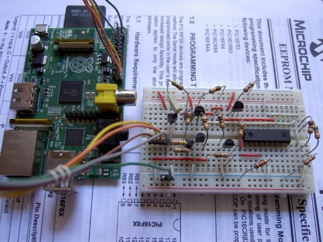
Direct GPIO programming means the Raspberry Pi itself generates the ICSP signals. Software toggles GPIO pins to send commands, addresses, data words, and read-back requests to the PIC. This approach is educational and inexpensive, but it depends heavily on software support for the exact PIC family.
Older projects such as Raspberry Pi PIC programmer tools, PICPgm-style workflows, RPiPIC experiments, and GPIO-based programmers show that the concept works. Some projects support classic 12-bit and 14-bit PIC devices such as PIC12 and PIC16 families. Others experiment with PIC18, PIC24, dsPIC, or PIC32 families. However, support is never universal. PIC programming algorithms differ across families, and even similar-looking chips can require different command sequences, memory layouts, configuration handling, or voltage entry methods.
2. Raspberry Pi With A PICkit Or Compatible Programmer
The second approach is to use the Raspberry Pi as the computer controlling a dedicated programmer such as a PICkit 2, PICkit 3, PICkit 5, or compatible tool. In this setup, the Raspberry Pi does not directly bit-bang ICSP lines. Instead, it runs command-line programming software and talks to the programmer over USB.
This is usually more reliable for real projects. Dedicated Microchip programmers are designed to handle voltage levels, device detection, programming voltage, verification, and a broad range of chips. A Raspberry Pi can still provide automation, remote access, and scripting, while the programmer handles the electrical heavy lifting. For many users, this is the sweet spot: less “mad scientist breadboard,” more “small production station that actually behaves on Mondays.”
Hardware You Need
The hardware depends on whether you are using direct GPIO or an external programmer. For a direct Raspberry Pi PIC programmer, the usual parts include:
- A Raspberry Pi with accessible GPIO pins.
- A PIC microcontroller supported by your chosen software.
- A breadboard or programming socket.
- Jumper wires and an ICSP header.
- Resistors for current limiting and pull-ups or pull-downs.
- Level shifting or buffering between the Pi and the PIC when needed.
- A safe VPP/MCLR circuit if the target requires high-voltage programming.
- A stable power supply for the target circuit.
- Common ground between Raspberry Pi and target board.
The most important rule is simple: do not feed 5V into Raspberry Pi GPIO pins. The Pi is a 3.3V device. A mistake here can turn a useful computer into a decorative coaster. If your PIC runs at 5V, protect the Pi with level shifters, buffers, resistors, or open-drain style interfaces where appropriate.
Understanding VPP And MCLR
Many PIC microcontrollers enter programming mode through the MCLR/VPP pin. Depending on the device, programming may require applying a voltage higher than normal logic level. Some newer or low-voltage devices can be programmed without a high-voltage entry, but many classic PICs expect a specific sequence involving VDD and VPP.
This is where beginners often get stuck. The Pi cannot generate a 9V, 12V, or similar programming voltage directly from GPIO. If your selected PIC needs high-voltage programming, you need a transistor-based or MOSFET-based switching circuit controlled by the Pi, plus an appropriate external voltage source. You also need to follow the exact programming specification for the PIC model. Guessing VPP is like seasoning soup with a fire extinguisher: dramatic, but rarely correct.
Software Options For Raspberry Pi PIC Programming
On the software side, you have three broad choices: open-source GPIO programmers, command-line tools for PICkit-style hardware, or custom scripts written for a specific PIC family.
Open-Source GPIO Programmers
Several community projects have explored PIC programming directly from the Raspberry Pi. Tools such as RPiPIC, picberry, and other experimental programmers use GPIO pins to implement the programming protocol. These tools are valuable learning resources, especially because they reveal the programming process step by step.
The limitation is device coverage. A program written for a PIC16F628A may not magically support a PIC18F4550 or PIC24FJ device. Before building the circuit, check whether your exact chip is listed as supported. Also check whether the tool handles configuration words, oscillator settings, code protection bits, EEPROM memory, and verification.
PICkit Command-Line Workflows
If you use a PICkit programmer, the Raspberry Pi can act as a compact Linux host. Command-line tools make it possible to write scripts such as:
This is useful for repeatable workflows. A script can erase the chip, program the HEX file, verify memory, report success, and save a timestamped log. Add a simple button and LED, and you have a friendly programming jig that does not require a monitor, keyboard, or heroic patience.
Basic Workflow: From HEX File To Programmed PIC
Step 1: Identify Your PIC Device
Start with the full part number printed on the chip. “PIC16” is not enough. You need the exact model, such as PIC16F877A, PIC12F675, PIC18F2550, PIC24FJ64GA002, or another specific device. Then download the datasheet and programming specification. The datasheet tells you pin functions and electrical limits. The programming specification tells you how the device enters programming mode and how memory is written.
Step 2: Choose Direct GPIO Or PICkit Control
If your goal is education, direct GPIO programming is fascinating. If your goal is reliability, a dedicated programmer controlled by the Raspberry Pi is usually better. For production, repair work, or chips you cannot easily replace, use the more reliable method. Learning is fun; accidentally locking configuration bits because you rushed is less fun.
Step 3: Wire The ICSP Header
Connect VSS to ground, VDD to the correct target supply, PGC to the programming clock line, PGD to the programming data line, and MCLR/VPP to the reset or programming voltage circuit. Keep wires short. Long breadboard wires can add noise, especially when timing matters. If the chip is installed in a larger circuit, make sure other components are not loading the programming pins too heavily.
Step 4: Power Carefully
Decide whether the Raspberry Pi, programmer, or external supply powers the target. Never let two power supplies fight each other. If the PIC board has its own supply, configure your programmer accordingly. Confirm voltage with a multimeter before connecting GPIO. This one-minute check can save an afternoon of detective work.
Step 5: Program And Verify
Load the HEX file, run the programming tool, and always verify after writing. Verification reads the programmed memory back and compares it with the expected data. If verification fails, do not immediately blame the chip. Check wiring, VPP, target voltage, device selection, oscillator configuration, and whether the software truly supports that PIC.
Common Problems And How To Fix Them
The Device Is Not Detected
Device detection failures usually come from wiring errors, missing ground, incorrect MCLR handling, wrong voltage, unsupported chip, or swapped PGC and PGD lines. The classic mistake is assuming the pinout from one PIC applies to another. PIC chips are not a family of identical twins; they are more like cousins who share a last name and disagree about furniture placement.
Programming Starts But Verification Fails
Verification failure can point to unstable power, weak VPP, signal-level problems, excessive capacitance on MCLR, or software mismatch. If the PIC is in a circuit, disconnect loads from the programming pins or add isolation resistors in the board design. Good ICSP-friendly design matters.
The Raspberry Pi Reboots Or Acts Strange
This can happen if the target circuit draws too much current from the Pi or if wiring injects noise into the Pi’s power rails. Use a proper external supply for the target when needed. Keep grounds common, but do not ask the Pi’s 3.3V pin to power a whole laboratory of parts. It is a GPIO header, not a power station wearing a tiny hat.
Best Practices For Reliable PIC Programming
For a dependable Raspberry Pi PIC programmer setup, keep the design simple and repeatable. Use a labeled ICSP connector. Add current-limiting resistors where appropriate. Protect the Pi’s GPIO with level shifting. Use a stable power supply. Keep programming wires short. Confirm the exact PIC model in software. Store known-good HEX files in a version-controlled folder. After programming, verify and log the result.
For boards you design yourself, make ICSP access part of the schematic from day one. Bring out VPP/MCLR, VDD, VSS, PGC, and PGD to a header or test pads. Avoid placing heavy capacitors directly on MCLR unless the programming tool can handle it. Make sure other components connected to PGC and PGD do not prevent programming. A little planning here saves a lot of “why does this board hate me?” later.
When A Raspberry Pi PIC Programmer Makes Sense
A Raspberry Pi as a PIC programmer makes sense when you enjoy embedded learning, need automation, want a headless programming station, or are working with supported older PIC devices. It is also useful for labs, classrooms, hobby benches, and small repair setups where flexibility matters more than polished commercial software.
However, it is not always the best choice. If you are programming many device families, debugging complex firmware, or supporting production work with strict quality requirements, a modern Microchip programmer is a safer investment. A PICkit, ICD, or similar tool gives broader support and fewer homemade surprises. The Raspberry Pi can still be part of that workflow as the command-line host, which is often the most practical combination.
Example Project Idea: Headless Firmware Station
Here is a realistic example. Suppose you build a small batch of LED controller boards using a PIC16 device. You compile firmware on your main computer and copy the HEX file to a Raspberry Pi on the workbench. The Pi is connected to either a protected GPIO programmer circuit or a USB PICkit. A shell script programs the chip, verifies it, and flashes a green LED when successful. If programming fails, a red LED turns on and the script writes an error log.
This setup is simple, but powerful. It reduces repetitive clicking, keeps firmware versions organized, and helps prevent mistakes. It also makes the process friendly for someone who only needs to insert a board and press a button. That is where the Raspberry Pi shines: it turns a programming task into a small automated appliance.
Safety And Caution Notes
Before wiring anything, remember that the Raspberry Pi GPIO header is not forgiving. Always check voltage levels. Use a multimeter. Read the PIC datasheet. Confirm whether the target requires high-voltage programming. Do not connect VPP directly to a GPIO pin. Do not assume every online schematic applies to your exact chip. And if something gets hot, unplug first and investigate second.
The goal is not to build the cheapest possible programmer at any cost. The goal is to build a programmer that works reliably without damaging the Raspberry Pi, the PIC, or your enthusiasm for electronics. Enthusiasm is harder to replace than a resistor.
Extra Experience: Lessons From Using A Raspberry Pi As A PIC Programmer
The first thing you learn when using a Raspberry Pi as a PIC programmer is that “simple” and “easy” are not the same word. The ICSP interface is simple because it uses only a few pins. But making it reliable requires understanding power, timing, voltage thresholds, device families, and software support. A five-wire programmer can still produce fifty different questions if one wire is in the wrong row of the breadboard.
One practical experience is to start with a well-known, older PIC that your chosen software definitely supports. Do not begin with a rare chip pulled from a mystery appliance unless you enjoy debugging in the fog. A common PIC12 or PIC16 device is better for learning because examples, pinouts, and programming notes are easier to find. Once you can program, erase, read, and verify that chip repeatedly, then move to more ambitious devices.
Another lesson is that verification is not optional. When a tool says “program complete,” that sounds comforting, but the real confidence comes from reading memory back and comparing it. A chip can appear programmed while configuration bits are wrong, oscillator settings are unsuitable, or EEPROM data was skipped. Verification is the quiet friend who tells you the truth before your circuit embarrasses you in public.
Power supply behavior also matters more than beginners expect. Some PICs behave differently at different VDD levels. Some target circuits draw more current than expected. Some breadboards have poor connections that create intermittent failures. If programming fails randomly, do not change five things at once. Measure VDD. Measure VPP if used. Check ground continuity. Wiggle nothing while testing. Electronics troubleshooting rewards calm detective work, not dramatic cable shaking.
The Raspberry Pi is especially useful when you want automation. A small script can make the process repeatable: select the device, program the HEX file, verify, log the serial number, and show a result. You can even run the Pi headless over SSH. This is convenient when the programmer is mounted inside a jig or attached to a production fixture. Instead of opening a full desktop IDE, you use one command and get one clear result.
Still, there is a point where a dedicated programmer becomes worth it. If your project involves many PIC families, debugging, breakpoints, production programming, or customer hardware, a proper Microchip tool saves time. The Raspberry Pi direct-GPIO route is excellent for learning and special-purpose programming, but a PICkit-style device is better when reliability and broad support matter. The best setup may combine both: Raspberry Pi for automation, PICkit for electrical correctness.
In my view, the most valuable part of this project is not saving money. It is learning how microcontrollers are actually programmed. You stop thinking of firmware upload as magic and start seeing it as a sequence of electrical events. The Raspberry Pi becomes more than a tiny Linux box; it becomes a bridge between software and silicon. And yes, when the first PIC successfully blinks an LED after being programmed by your Pi, it feels oddly heroic. It is just an LED, but emotionally, it is fireworks.
Conclusion
Using a Raspberry Pi as a PIC programmer is a smart, educational, and surprisingly practical project when you respect the electrical details. The Pi can directly control ICSP lines for supported devices, or it can serve as a compact Linux host for a dedicated PIC programmer. The direct GPIO approach is excellent for learning how PIC programming works under the hood. The PICkit-plus-Pi approach is better for reliability, broader chip support, and repeatable workflows.
The key is preparation. Know your PIC model, read the datasheet, protect the Raspberry Pi GPIO, manage VPP correctly, verify every programming operation, and keep the wiring clean. Do that, and the Raspberry Pi becomes more than a single-board computer. It becomes a flexible embedded programming workstation small enough to hide under a coffee mug, though hiding electronics under coffee is still a terrible idea.
Note: This article is written for educational and technical publishing purposes. Always verify the exact datasheet and programming specification for your PIC device before connecting hardware.