A CNC flat coil winder is one of those workshop machines that looks simple until you try to build one. Then the machine quietly laughs, snaps a strand of magnet wire, and reminds you that precision is not a personality traitit is an engineering requirement. The idea is straightforward: guide fine copper magnet wire along a programmed path so it forms a flat spiral, oval, rectangular, or custom-shaped coil. The reality involves motion control, wire tension, G-code, tool alignment, stepper motor torque, and enough tiny mechanical decisions to make a coffee mug feel like precision tooling.
The phrase “Stepper Motor Mods Improve CNC Flat Coil Winder” points to a clever maker-style solution: modify the stepper-driven tool head so the wire exits closer to the true center of motion. That change may sound small, but in coil winding, small errors are the gremlins wearing lab coats. When the wire feed point lags behind the machine’s actual centerline, the G-code path no longer matches where the copper lands. On a flat coil, that means uneven spacing, distorted turns, inconsistent adhesive contact, and coils that look like they were designed by a nervous spider.
What Is a CNC Flat Coil Winder?
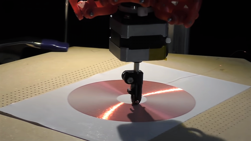
A CNC flat coil winder is a computer-controlled machine that lays magnet wire onto a flat surface instead of winding it around a traditional bobbin. Some machines use a Cartesian gantry, while others adapt a delta-style 3D printer frame. Instead of extruding plastic, the tool head dispenses wire onto adhesive paper, film, tape, or another substrate. The resulting coil can be a circular spiral, square spiral, racetrack shape, toroidal-inspired pattern, or experimental geometry.
Flat coils are useful in inductors, antennas, wireless power projects, sensors, electromagnetic experiments, and prototype motor or generator components. They are also attractive to makers because they allow custom shapes without waiting for a factory, ordering specialty tooling, or explaining to a supplier why you need “just three weird coils for science.”
Why Stepper Motors Are the Natural Choice
Stepper motors are popular in CNC machines because they move in controlled increments. A typical 1.8-degree stepper has 200 full steps per revolution. With microstepping drivers, that motion can be divided into much smaller increments, giving smoother motion and reducing vibration. For a coil winder, smooth movement is not just a luxury. It helps keep the wire path clean and repeatable.
Unlike a basic DC motor, a stepper motor can hold position when energized. That is valuable when the tool head must pause, change direction, or trace a tight curve. The controller sends step and direction signals, and the driver regulates current through the motor windings. Common hobby CNC setups use Arduino-compatible control boards, GRBL firmware, CNC shields, and drivers such as the A4988 or DRV8825. More advanced systems may use Trinamic-style drivers, closed-loop steppers, or external digital stepper drives for smoother torque and better thermal performance.
The Core Problem: The Wire Must Exit Where the Math Thinks It Exits
In CNC work, the machine does not care where you wish the tool were. It only follows coordinates. If the tool tip is offset from the machine’s assumed center, the finished part is wrong. In a router, this shows up as dimensional error. In a laser cutter, it may show up as an alignment issue. In a flat coil winder, it shows up as copper wire landing in the wrong place.
Early flat coil winder designs often used a passive roller or guide mounted near the tool head. The issue is that the actual contact point can trail behind the center axis, especially when the machine changes direction. The result is a path that looks correct in software but shifts in the physical world. That lag becomes more visible in tight spirals, curves, and small-radius turns.
The clever stepper motor modification solves this by placing the wire path through the motor shaft itself. By drilling through the shaft of a NEMA 17-style stepper motor, the builder creates a rotating wire guide where the feed point can stay centered. The motor can then actively swivel the tool so the roller or guide faces the correct direction as the X and Y axes move. It is the mechanical equivalent of telling the wire, “No wandering off. We discussed this.”
How the Stepper Motor Mod Works
1. A Hollow Shaft Creates a Centered Wire Path
The most important change is creating a passage through the stepper motor shaft. Fine magnet wire can pass through the center of the rotating tool. That keeps the feed point aligned with the tool’s rotational axis, which simplifies compensation and improves the relationship between G-code and real-world wire placement.
2. The Tool Head Actively Swivels
A passive roller follows the wire path after the fact. An actively controlled stepper tool head can rotate in sync with X-Y movement. This matters when the machine traces curves or changes direction. The roller remains oriented to lay the wire neatly instead of dragging it sideways.
3. A Preload Spring Keeps Contact Consistent
Flat coil winding often requires light pressure so the wire sticks to the substrate without scraping, stretching, or deforming. A preload spring can help the roller maintain steady contact. Too much pressure can damage insulation; too little pressure can leave loose sections that lift off the adhesive. The goal is “firm handshake,” not “hydraulic press.”
4. Rotor Orientation and Mechanical Balance Matter
Disassembling and modifying a stepper motor is not a casual operation. The rotor, bearings, magnets, and shaft alignment all affect performance. Any drilling must be centered and clean. Burrs must be removed so the magnet wire does not scrape. If the rotor is reversed or reassembled incorrectly, the motor may bind, lose torque, or behave like it has had too much espresso.
Why This Improves Coil Quality
The improvement is not just mechanical neatness. It directly affects coil performance. A flat spiral coil’s electrical behavior depends on geometry: number of turns, spacing between turns, wire diameter, inner radius, outer radius, and total conductor length. Uneven spacing changes inductance, resistance, capacitance, and repeatability. For experiments, that may lead to confusing measurements. For functional parts, it may reduce efficiency or create hot spots.
When the wire exits at the rotational center and the tool orientation is controlled, the coil winder can produce cleaner shapes with more predictable spacing. That is especially important for wireless power coils, sensor coils, RFID experiments, and compact inductors where geometry is not decorationit is the circuit.
Important Design Considerations for CNC Flat Coil Winding
Wire Tension
Magnet wire tension is one of the most overlooked details in coil winding. Too little tension creates loops and uneven placement. Too much tension stretches the copper, increases resistance, damages enamel insulation, or breaks the wire. Fine wire is especially unforgiving. A practical design may use felt pads, adjustable drag, spring-loaded arms, dancer mechanisms, or commercial tensioners. The key is consistency.
Microstepping and Driver Current
Microstepping can make motion smoother, but it is not magic dust. The driver current limit must be set correctly. If current is too low, the motor skips steps. If it is too high, the motor and driver overheat. On small CNC machines, skipped steps are disastrous because the controller usually does not know the motor missed its move. The machine keeps going confidently, like a GPS giving directions into a lake.
G-Code Path Planning
The G-code must account for coil spacing, feed rate, tool orientation, and the physical behavior of the wire. A flat spiral can be generated mathematically, but the machine must handle acceleration, direction changes, and radius transitions. For a delta-style machine, kinematics add another layer. Tool offset compensation becomes critical if the wire contact point is not centered, which is exactly why the stepper motor modification is so useful.
Substrate and Adhesive
Many flat coil experiments use adhesive paper or tape to hold the wire in place. The adhesive must grip the enamel-coated copper without contaminating it or allowing the wire to float. For prototypes, double-sided tape or transfer adhesive can work. For more durable parts, epoxy, varnish, Kapton tape, or laminated films may be used. Heat rating matters if the coil will carry significant current.
Wire Guide Surface Finish
Any guide hole, nozzle, roller, or tube that touches magnet wire should be smooth. A tiny burr can scrape insulation and create a hidden short. Ceramic eyelets, polished brass tubes, PTFE guides, or carefully deburred stainless parts can reduce friction. If the wire passes through a drilled shaft, the entrance and exit should be rounded and polished.
Specific Example: Turning a 3D Printer Into a Coil Winder
A delta 3D printer is an appealing starting point because it already has smooth motion, a controller, stepper motors, and a moving tool platform. Remove the hot end, install a wire-feeding tool, and the machine becomes a CNC wire plotter. Instead of plastic filament, it lays copper magnet wire.
The first version may work with a simple roller, but the limitations appear quickly. A passive roller does not always place the wire exactly under the theoretical tool center. When winding a circular spiral, the deviation may be tolerable. When winding complex shapes, tight corners, or small coils, the offset becomes obvious. Adding a stepper-controlled rotating tool head transforms the system from a wire dragger into a more precise wire placement machine.
Benefits of the Stepper Motor Mods
- Better tool-center alignment: The wire exits closer to the machine’s intended coordinate point.
- Cleaner turns: The roller can follow curves without pulling the wire sideways.
- Improved repeatability: Similar G-code files produce more consistent coils.
- More geometry options: The machine can handle spirals, rounded rectangles, and custom paths more accurately.
- Less software compensation: Centering the wire mechanically reduces the need for complicated offset math.
- Better contact pressure: A spring-loaded roller helps keep the wire attached to the substrate.
Possible Risks and Trade-Offs
Modifying a stepper motor is not risk-free. Drilling a shaft can weaken it, introduce runout, or damage bearings if chips enter the motor. The motor may lose some mechanical robustness, and reassembly requires care. There is also the question of heat. If the tool motor runs constantly while holding position, heat can transfer into nearby printed parts, guides, or adhesive surfaces.
Another trade-off is control complexity. An actively swiveling tool requires coordinated motion. The controller must know where the tool should point during the path. That may require custom G-code generation, post-processing, or firmware adjustments. Still, for builders chasing precision, this extra complexity is worth it.
Practical Tips for Building a Better CNC Flat Coil Winder
Start With Large Coils First
Large spirals expose fewer problems than tiny high-density coils. Begin with wider spacing and thicker wire. Once the machine behaves, move toward finer magnet wire and tighter turns.
Calibrate Steps Per Millimeter Carefully
Stepper accuracy depends on motor steps, pulley size, belt pitch, lead screw pitch, and microstepping settings. A small calibration error becomes visible over many turns. Measure actual movement with calipers and update firmware settings before blaming the wire, the moon, or your favorite slicer.
Use Conservative Feed Rates
Flat coil winding rewards patience. High speed can cause the wire to lift, skid, or break. Slower movement gives the roller time to press the wire evenly into the adhesive.
Keep the Wire Path Short and Smooth
Every guide, bend, and spool drag point adds friction. A clean wire path reduces tension spikes. Mount the spool so it unwinds smoothly, and avoid sharp bends before the tool head.
Document Every Successful Setting
Record wire gauge, feed rate, adhesive type, roller pressure, driver current, microstepping, and coil geometry. When a coil finally comes out perfect, you will want to reproduce it. Trusting memory is how workshops become archaeological sites of forgotten settings.
Workshop Experience: Lessons From Tuning a Stepper-Driven Flat Coil Winder
The first experience most builders have with a CNC flat coil winder is humbling. On paper, the machine looks easy. The G-code draws a spiral. The stepper motors move. The wire follows. Everyone claps. In practice, the first coil often looks like a copper cinnamon roll that lost a bar fight. That is normal.
The biggest lesson is that wire behaves like a mechanical component, not a line in a drawing. It has stiffness, memory, friction, insulation thickness, and a strong desire to spring away from the exact place you wanted it. A modified stepper tool head helps because it reduces the mismatch between programmed motion and wire placement. When the wire exits through the rotating center, the machine stops fighting its own geometry.
Another lesson is that small adjustments matter. A quarter-turn on a tension screw can change the coil from loose to clean. A slightly polished guide hole can stop random insulation scratches. A slower feed rate can turn a messy outer loop into a smooth turn. Better current tuning on the stepper driver can remove chatter that was shaking the roller just enough to create uneven spacing. None of these changes is dramatic alone, but together they make the machine feel less like a prototype and more like a tool.
Adhesive choice is also more important than many builders expect. Some tapes grab too aggressively, making correction impossible. Others release the wire at corners. A good substrate holds the wire during winding but does not gum up the guide or roller. For experimental coils, it helps to test a short straight line, a tight curve, and a full spiral before committing to a long run.
The most satisfying moment comes when the machine begins laying copper exactly where expected. A flat spiral grows turn by turn, evenly spaced, quietly forming a useful electromagnetic part out of a spool of wire and a stubborn idea. That is the charm of this project. It combines CNC motion, electronics, mechanics, and material handling in one compact puzzle. The stepper motor mod is not just a trick; it is a reminder that better machines often come from moving the physical tool closer to the mathematical model.
Conclusion
Stepper motor mods can significantly improve a CNC flat coil winder by solving one of its most frustrating problems: inaccurate wire placement caused by tool offset and passive guide lag. By routing magnet wire through a modified stepper shaft and actively rotating the tool head, builders can keep the wire feed point aligned with the machine’s intended path. Add proper tension control, calibrated microstepping, smooth guides, and careful G-code planning, and the result is a machine capable of producing cleaner, more repeatable flat coils.
This kind of project captures the best part of maker engineering. It is practical, a little strange, deeply educational, and just dangerous enough to remind you not to drill motor shafts while daydreaming. For anyone experimenting with wireless power, inductors, sensors, custom electromagnetic devices, or simply the joy of precision motion, a CNC flat coil winder is a rewarding machine to buildand stepper motor modifications may be the upgrade that turns it from “almost working” into “beautifully useful.”
Note: This article is written as original educational content for web publishing and is based on established CNC motion-control, stepper-motor, magnet-wire, and coil-winding practices.