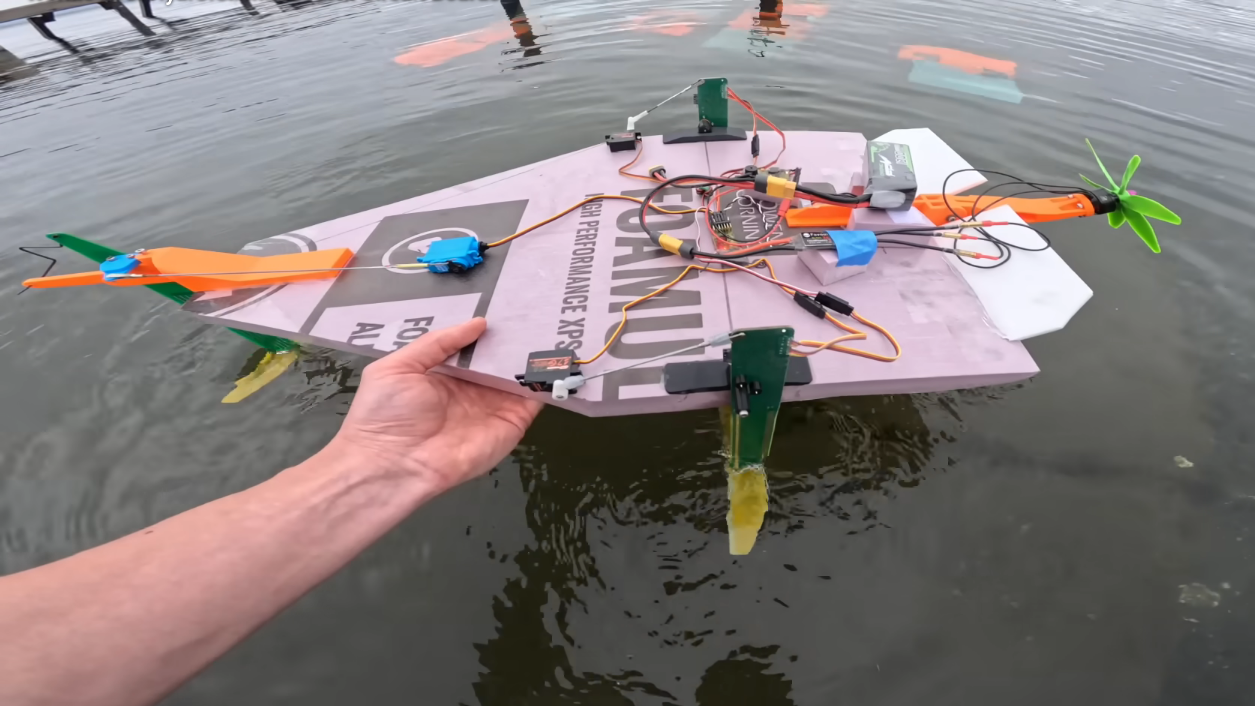
Every so often, the maker world produces a project that sounds like a typo, looks like a dare, and somehow ends up being a genuinely clever engineering lesson. “A PCB can be a hydrofoil” belongs firmly in that delightful category. A printed circuit board is supposed to sit politely inside a gadget, routing signals, holding components, and pretending it is not the most important piece of the machine. A hydrofoil, meanwhile, is supposed to slice through water, lift a hull, reduce drag, and make a boat look as if it has discovered aviation but refused to leave the lake.
Put those two ideas together and you get something wonderfully weird: a remote-controlled hydrofoil that uses PCB material not just as an electronic platform, but as part of the physical structure touching the water. It is one of those projects that makes engineers nod, hobbyists grin, and traditional boatbuilders quietly reach for a stronger coffee.
The genius of the idea is not that a PCB magically becomes a perfect marine material. It does not. The genius is that a PCB is already a layered fiberglass composite with copper traces, repeatable manufacturing, precise geometry, and low-cost production. In other words, it is not just a board. It is a tiny, factory-made structural part that happens to know how to carry electricity.
Why a PCB Hydrofoil Is Less Ridiculous Than It Sounds
At first glance, using a printed circuit board as a hydrofoil component sounds like building a skateboard out of toast. But once you look at what standard FR4 PCB material actually is, the idea starts behaving itself. FR4 is made from woven fiberglass cloth bonded with epoxy resin. That combination gives ordinary circuit boards their stiffness, electrical insulation, and mechanical durability. It is not marine-grade carbon fiber, but it is not wet cardboard either.
Fiberglass has a long history in boats, surfboards, radio-controlled models, and lightweight structures. A PCB simply adds one more trick: copper traces can be designed directly onto the surface. That means a hydrofoil mast can become both a physical support and a sensor platform. Instead of bolting a separate sensor onto a wet, vibrating, tiny structure, the sensor can be part of the structure from the beginning. That is elegant in the same way a Swiss Army knife is elegant, except this one has solder mask and questionable life choices.
In the rctestflight-style PCB hydrofoil concept, the PCB mast is not merely a bracket. It carries sensing electronics close to the waterline, where altitude information matters most. The system can read how much of the mast is submerged and use that data to adjust the hydrofoil’s behavior. That turns the PCB into a mechanical part, an electrical part, and a feedback device all at once.
How Hydrofoils Work: The Short Version With Less Splashing
A hydrofoil works by creating lift underwater. As the boat moves forward, water flows over the submerged wing-like foil. At sufficient speed, the foil generates enough lift to raise the hull above the water. Once the hull is lifted, less of the boat is dragging through the surface, which can reduce resistance and improve speed or efficiency.
This is why hydrofoils look so futuristic. The boat is not floating in the usual lazy way; it is balancing on underwater wings. The result can be smooth, fast, and efficient, but also demanding. Hydrofoils need stability. Too little lift and the hull slaps back onto the water. Too much lift and the craft can breach, stall, or wobble like a shopping cart with one rebellious wheel.
Small RC hydrofoils are especially tricky because everything happens quickly. The craft is light, the water surface is messy, and tiny pitch changes can become dramatic. A sensor that measures height quickly and accurately is not a luxury. It is the difference between graceful foiling and a very small boat doing a dramatic impression of a confused dolphin.
The Clever Part: Turning the PCB Into a Water-Level Sensor
The most interesting part of the PCB hydrofoil idea is not simply “FR4 is stiff enough.” The real magic is using the board as a sensor. A hydrofoil needs to know its altitude relative to the water surface. Traditional small projects might use ultrasonic sensors, pressure sensors, or external probes. Those can work, but they add hardware, mounting problems, wiring, and latency.
A PCB mast can put the sensor exactly where the measurement happens. Early versions of projects like this often start with resistive sensing because it is simple: expose conductive traces, let water connect them, and measure the change. Unfortunately, water is not a polite laboratory assistant. Salt water conducts, corrodes, and encourages electrochemical reactions. Resistive sensors can self-corrode quickly, especially when current flows through exposed metal in an electrolyte.
That is why capacitive sensing is so attractive. Instead of relying on direct electrical contact through water, a capacitive sensor measures changes in the electric field around the board. Water has a high dielectric constant compared with air, so the sensor can detect whether a section of the mast is in water without needing exposed conductive tracks to become sacrificial snacks for corrosion.
This is where microcontrollers like the ESP32 make the project feel modern. A small, low-cost microcontroller with wireless capability and sufficient processing power can sit close to the sensor, read the signal, process it, and feed data into a control loop. In a normal boat, that sounds like overkill. In a tiny experimental hydrofoil, overkill is often just engineering wearing a nicer hat.
Fast Feedback Is the Secret Sauce
Hydrofoil control is all about timing. If the craft is rising too high, the controller must react before the foil pops out of the water. If it is sinking, it must restore lift before the hull drags. The more direct the sensor data, the better the control loop can behave.
A close-coupled PCB sensor reduces the distance between measurement and decision-making. Instead of collecting water height data from a separate module mounted elsewhere, the mast itself becomes the measurement surface. That can improve response time and reduce mechanical clutter. In small RC vehicles, clutter is not just ugly; it adds weight, drag, wiring failures, and new places for water to practice its hobby of ruining electronics.
Once sensor data is available, a PID controller can adjust servos that change foil angle or mast position. PID stands for proportional, integral, and derivative control. In plain English, it is a control method that asks three questions: How wrong are we right now? How wrong have we been for a while? And how fast is the wrongness changing? It is basically anxiety with math, but when tuned properly, it keeps machines stable.
In a PCB hydrofoil, each mast can potentially have its own sensor and local microcontroller. That allows the control system to respond to differences between sides, helping with pitch, roll, and altitude. It is not just a floating toy; it becomes a miniature robotics problem with water, lift, materials science, and embedded electronics all sharing one very damp stage.
Why Structural PCBs Are Becoming More Interesting
For decades, PCBs were treated mostly as electronic real estate. Components lived on them. Signals traveled through them. Screws occasionally held them in place. But modern makers and engineers increasingly see PCBs as structural materials too. They can become enclosures, robot chassis, wearable frames, artistic sculptures, keyboard plates, test fixtures, and now, apparently, hydrofoil masts.
The reason is simple: PCB fabrication is precise, affordable, and accessible. A designer can draw a part in CAD-like PCB software, define outlines, slots, copper areas, mounting holes, labels, and layer features, then order a small batch from a board house. The result arrives flat, repeatable, and ready for soldering. That is an incredible advantage for prototypes.
Traditional mechanical fabrication often requires cutting, drilling, bonding, and finishing. PCB manufacturing gives makers a shortcut to complex flat composite parts with integrated electrical features. Need a sensor shape? Draw it. Need mounting holes? Add them. Need a trace that runs through the mast to a processor? Route it. Need a label that says “front” because future-you will otherwise install it backward at midnight? Silkscreen it with dignity.
The Hard Truth: Water Still Wins If You Get Lazy
As charming as the PCB hydrofoil idea is, water remains a ruthless opponent. Fresh water is troublesome enough. Salt water is the final boss. It attacks exposed copper, creeps into cracks, encourages corrosion, and turns small electrical mistakes into big reliability lessons.
That means a PCB used near water must be designed differently from a PCB used inside a desk gadget. Exposed metal should be minimized. Solder joints should be protected. Edges may need sealing because PCB edges can expose fiberglass and resin layers. Coatings, potting, conformal protection, and careful connector choices become important. In marine electronics, the phrase “it worked on the bench” is often followed by “and then the lake explained reality.”
Mechanical strength also matters. A hydrofoil mast sees bending loads, vibration, impacts, and twisting. FR4 is stiff, but it is not indestructible. Copper can delaminate if abused. Solder joints can fatigue. Thin boards can flex too much, while thick boards add drag and weight. If the PCB is used as a load-bearing member, the design should respect grain direction, thickness, mounting geometry, and stress concentration around slots or holes.
For a toy-scale experimental craft, these tradeoffs are acceptable and educational. For anything carrying a person, a PCB hydrofoil should stay in the land of “interesting idea,” not “weekend transportation.” There is a big difference between a clever RC prototype and a ride-on vehicle that needs serious marine engineering, redundancy, waterproofing, and safety validation.
What This Project Teaches About Modern Making
The most valuable lesson is not that every circuit board secretly wants to become a boat part. The lesson is that boundaries between disciplines are getting thinner. A mechanical part can be an electrical part. A sensor can be a structure. A prototype can be ordered from a PCB manufacturer instead of machined from stock. A hydrofoil can become a robotics platform.
This is where modern maker culture shines. It takes a normal material and asks an abnormal question. Can a PCB be a mast? Can a copper pattern become a water-level sensor? Can a microcontroller live close enough to the action to make control smoother? Can a design be made simpler by combining jobs instead of adding parts?
That kind of thinking is powerful beyond RC boats. Structural PCBs can be useful in drones, small robots, scientific instruments, lab fixtures, environmental sensors, educational kits, and compact consumer devices. Any time a project needs a flat rigid part with integrated wiring, PCB-as-structure deserves consideration.
Design Analysis: Why the PCB Hydrofoil Concept Works
1. It combines structure and sensing
The mast is already in contact with the water, so turning it into a water-level sensor is efficient. Instead of adding a separate probe, the project uses the surface that already exists. This reduces part count and can improve measurement relevance.
2. It uses manufacturing precision
PCB fabrication can produce repeated shapes with tight alignment between outline, copper, solder mask, vias, and mounting features. For a small hydrofoil prototype, repeatability helps when comparing design changes.
3. It shortens the feedback path
Local sensing and microcontroller processing can make the control loop faster. That matters because hydrofoils are sensitive to altitude and pitch. A slow system reacts after the exciting mistake has already happened.
4. It encourages modular experimentation
Want a different sensor pattern? Change the copper layout. Want a thicker mast? Order a different board thickness. Want better sealing? Revise the solder mask or add coating. PCB iteration is fast compared with many traditional composite fabrication workflows.
5. It makes learning visible
Students and hobbyists can see how electronics, hydrodynamics, control theory, and materials interact. The boat becomes a floating classroom with a propeller and a sense of humor.
Where the Idea Could Go Next
A future PCB hydrofoil kit could become an excellent educational platform. Imagine a small RC craft where learners can adjust PID settings, compare resistive and capacitive sensing, test different foil angles, log altitude data, and understand why waterproofing is not optional. It would teach embedded systems, signal processing, fluid dynamics, and mechanical design in one project.
There is also room for better materials. Standard FR4 is convenient, but alternative PCB substrates or hybrid mechanical parts could improve stiffness, water resistance, or long-term durability. Designers might use thicker boards, plated slots, sealed edges, flexible interconnects, or modular sensor strips. Coatings could protect exposed conductors while still allowing capacitive measurement. The PCB does not need to be the entire answer; it can be the clever part of a larger answer.
The most exciting possibility is not a giant PCB boat. Please do not build a giant PCB boat unless your insurance company has a strong sense of adventure. The exciting possibility is smarter integration. When physical parts carry sensing and computation, machines can become lighter, cleaner, and easier to assemble.
Experience Notes: What Builders Learn From a PCB Hydrofoil Project
Anyone who has spent time around small experimental machines knows that the first prototype is rarely a masterpiece. It is more like a negotiation with physics. A PCB hydrofoil project captures that experience perfectly. On paper, the idea looks neat: use FR4 as the mast, print sensor traces on it, add a microcontroller, tune the controller, and enjoy smooth foiling. In practice, every subsystem politely introduces a problem you forgot to invite.
The first experience is usually material humility. PCB material feels strong in the hand, but water loads can surprise you. A part that seems rigid on the workbench may flex when pushed through water. A mounting hole that looks harmless may become the starting point for a crack. A solder joint that survived testing indoors may complain after vibration, moisture, and repeated impacts. The lesson is not that PCB material is bad. The lesson is that every material has a personality, and FR4’s personality is “stiff, useful, affordable, but do not get cocky.”
The second experience is sensor reality. Resistive water sensing is tempting because it is simple. Then corrosion shows up like an unpaid consultant. Capacitive sensing feels more refined, but it brings its own calibration challenges. Water conditions change. Air gaps matter. Coatings affect readings. Noise sneaks into the system. The best builders learn to treat sensor data as a conversation, not a commandment. Smooth filtering, sensible thresholds, and repeatable testing matter more than one heroic reading that looked great at 2 a.m.
The third experience is control tuning. PID control sounds tidy until the boat starts bouncing. Too much gain and the craft overcorrects. Too little gain and it reacts like it is waiting for written permission. The sweet spot depends on speed, weight, foil geometry, servo response, and water conditions. Tuning becomes part engineering, part patience, and part trying not to blame the lake.
The fourth experience is waterproofing discipline. Builders quickly learn that water finds every shortcut. Connectors need protection. Board edges need attention. Coatings need complete coverage. A tiny exposed pad can become a mystery failure. This is where good prototypes separate themselves from “technically it worked once” prototypes.
Finally, a PCB hydrofoil teaches the joy of integrated design. When the mast is also the sensor and the circuit carrier, the project becomes cleaner and more thoughtful. It rewards designers who think across categories instead of treating electronics, mechanics, and software as separate kingdoms. That is the real charm of the project. It is not just a PCB pretending to be a hydrofoil. It is a reminder that clever engineering often begins with asking a slightly silly question and taking the answer seriously.
Conclusion
A PCB can be a hydrofoil component, if the scale is right, the design is smart, and nobody asks it to carry a full-sized human across choppy water. The concept works because FR4 is a fiberglass-reinforced composite, PCB manufacturing is precise, and copper traces can turn a structural part into a sensor. Add a microcontroller, a control loop, and some careful waterproofing, and the humble circuit board becomes far more than a place for components to sit.
The project is funny because it sounds absurd. It is impressive because it is not actually absurd. It shows how modern prototyping rewards people who combine materials, electronics, software, and physics in unexpected ways. A PCB hydrofoil may not replace conventional marine engineering, but it absolutely earns its place in the gallery of maker projects that make you say, “Wait, that works?”
Note: This publish-ready HTML body intentionally excludes source links inside the article copy, while the content is based on real maker, PCB material, hydrofoil, and embedded-control references.