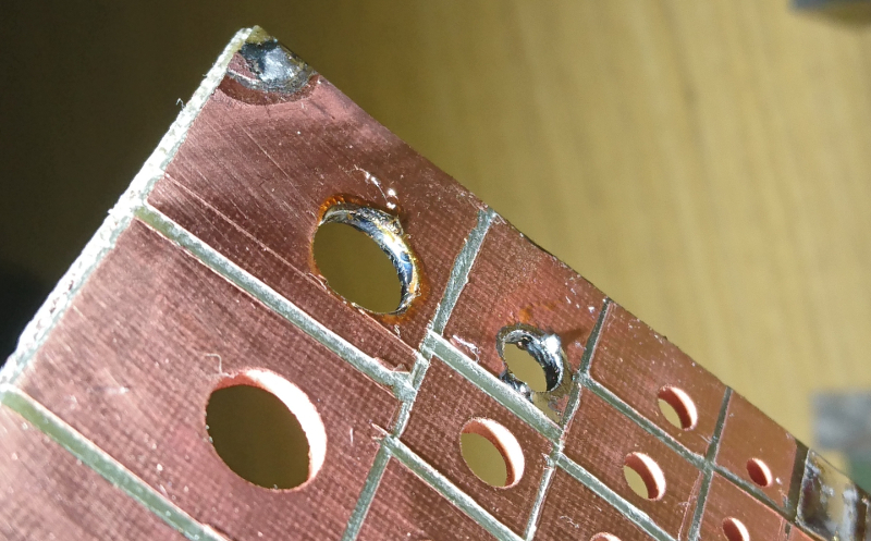
Note: This article is written in standard American English, fully rewritten for web publishing, and based on real PCB manufacturing and DIY electronics practices.
There is a special kind of impatience known only to electronics makers. It appears right after you finish routing a board, admire your neat little traces, and then remember that ordering a two-layer PCB means waiting daysor weekswhile your brilliant idea sits in a shopping cart somewhere, silently judging you. That is when the forbidden thought arrives: Why wait? Just plate your own PCB vias.
For hobbyists, hackers, robotics builders, and small-lab engineers, PCB via plating is one of those skills that sounds like wizardry until you break it down. A via is simply a tiny conductive tunnel that connects one copper layer of a printed circuit board to another. In a factory, these holes are drilled, cleaned, seeded with conductive material, and electroplated with copper until the inside wall becomes a reliable electrical path. At home, the same principle applies, though with more gloves, more testing, and a greater chance that your workbench starts looking like a science fair project with commitment issues.
Still, the idea is powerful. If you can make your own double-sided PCB and plate the through-holes yourself, you can prototype faster, repair boards creatively, and understand PCB manufacturing in a way no ordering form can teach. You also gain a healthy respect for why professional board houses charge money and use process controls instead of “looks shiny enough” as a quality standard.
What Are PCB Vias, and Why Do They Matter?
A printed circuit board is not just a flat green rectangle that makes electronics look official. It is a carefully organized stack of insulating material and copper pathways. When a signal needs to move from the top copper layer to the bottom layer, it needs a bridge. That bridge is the via.
The most common type is the through-hole via. It passes all the way through the board, from top to bottom, and the inside wall is coated with copper. Once plated, the via behaves like a vertical wire embedded inside the PCB. In a double-sided board, this allows traces to cross layers without using jumper wires. In multilayer boards, vias connect signal layers, power planes, ground planes, and thermal paths.
There are other via types too. Blind vias connect an outer layer to an internal layer without passing through the whole board. Buried vias connect only internal layers. Microvias are tiny laser-drilled structures used in high-density interconnect designs, especially where space is tighter than a maker’s budget after buying a new oscilloscope. But for DIY PCB via plating, through-hole vias are the star of the show because they are practical, visible, mechanically drillable, and easier to inspect.
Why Plate Your Own Vias Instead of Ordering Boards?
Professional PCB manufacturers are excellent. They can deliver clean solder mask, controlled drill tolerances, plated holes, surface finishes, silkscreen, impedance control, and quality inspection. For finished products, production runs, medical devices, automotive electronics, aerospace hardware, and anything that must survive abuse, outsourcing is usually the right choice.
But not every board is a production board. Sometimes you are testing a sensor breakout, building a robot controller, trying a weird analog circuit, or proving that your “small weekend project” has grown into a four-month relationship. In those cases, speed matters. If your home PCB process can produce a usable board the same day, plated vias can remove one of the biggest limitations of homemade double-sided PCBs.
Without plated vias, DIY builders often rely on small wire links, component leads soldered on both sides, rivets, eyelets, or awkward trace routing. These work, but they are slow and bulky. A plated via is cleaner. It preserves routing density, improves mechanical neatness, and lets the board behave more like a professionally fabricated PCB.
How Professional Via Plating Works
Factory via plating starts with drilling. The manufacturer drills holes where vias and plated through-holes are needed. The board then goes through cleaning and desmear steps to remove resin debris from the hole walls. This matters because copper will not reliably bond to dirty, glassy, or smeared laminate. If the hole wall is not prepared correctly, the copper barrel can crack, separate, or form voids.
Next comes a conductive seed layer. Since FR-4 laminate is not conductive, the hole wall needs a thin conductive coating before electroplating can build copper. Many professional processes use electroless copper deposition, a chemical method that lays down a thin copper layer without external current. After that, electrolytic copper plating thickens the barrel. The result is a continuous copper cylinder connecting the copper pads on different layers.
In higher-reliability manufacturing, plating thickness matters. Standards such as IPC-6012 define expectations for rigid printed boards, including hole-wall copper thickness for different reliability classes. A common practical target for many standard plated through-holes is around 20 to 25 microns of copper, though exact requirements depend on the board class, application, and manufacturer. That copper is not decorative. It handles current, survives thermal cycling, resists cracking, and keeps the circuit connected when real life starts shaking, heating, bending, and generally being rude.
The DIY Version: Same Physics, Smaller Kitchen-Lab Energy
DIY PCB via plating usually follows the same basic logic: drill the holes, make the hole walls conductive, then electroplate copper onto those conductive surfaces. The challenge is not understanding the concept. The challenge is making it repeatable.
One popular homebrew approach uses conductive graphite coating. Graphite can make the inside of the drilled holes electrically conductive enough to start copper deposition. The board is drilled, cleaned, coated with graphite, dried or cured, lightly sanded so graphite remains mainly inside the holes, and then placed in a copper electroplating bath. With the right current control, copper gradually deposits on the exposed conductive surfaces, including the hole walls.
This method is clever because it avoids some of the more complex chemistry of electroless copper. Instead of trying to reproduce a factory line, the maker uses a conductive bridge to get the plating started. Once copper begins to grow inside the via, the via becomes progressively better at accepting more copper. It is a little like convincing a shy trace to become a barrel of confidence.
Key Materials and Setup Considerations
1. Start With Clean Copper-Clad Board
Cleanliness is not optional. Oxidized copper, fingerprints, dust, drill debris, and oily residue can ruin plating adhesion. A clean board gives the conductive coating and copper deposit a better chance of bonding. Many DIY builders polish the copper surface lightly, wash away residue, and avoid touching the board with bare hands after cleaning.
2. Drill Carefully
Via plating starts with a hole, so bad drilling creates bad vias. Small carbide drill bits are fragile, especially in the 0.3 mm to 0.5 mm range. A wobbly drill press, dull bit, or impatient hand can create ragged holes, broken bits, and annular rings that look like they survived a raccoon attack. Use stable drilling equipment, accurate alignment, and pad sizes generous enough to tolerate small errors.
3. Respect the Annular Ring
The annular ring is the copper pad surrounding the drilled hole. It is the landing area that connects the trace to the plated barrel. If the hole is off-center or the pad is too small, the drill can break out of the ring and weaken the connection. For homemade boards, bigger rings are your friends. Yes, tiny vias look professional. No, your first home-plated board does not need to impersonate a smartphone motherboard.
4. Make the Hole Wall Conductive
Graphite coating is one practical method. Conductive ink, carbon-based coatings, or other conductive treatments can also be used in experimental workflows. The goal is to create a continuous conductive path from the top copper pad through the hole wall to the bottom copper pad. If the coating does not reach the inside of the hole, copper will not plate there. The via may look fine on the outside while being electrically useless inside, which is the PCB equivalent of wearing a tuxedo with no pants.
5. Use Controlled Current
Electroplating is not improved by simply “turning it up.” Too much current can produce rough, burnt, spongy, or uneven copper. Too little current may plate slowly or inconsistently. Constant-current control is usually preferred because plating depends on current density. The goal is smooth, even copper deposition, not a copper coral reef growing on your prototype.
6. Manage Bubbles and Surface Tension
Small holes trap air easily. If a bubble sits inside a via, the plating solution cannot contact that area, and copper cannot deposit properly. This is one reason very small vias are harder to plate at home. Gentle agitation, wetting agents, careful board positioning, and patient inspection can help. If you are plating tiny holes, assume bubbles are plotting against you personally.
Common DIY Via Plating Problems
Thin or Missing Copper Inside Small Holes
Small holes are difficult because conductive coating may not penetrate completely, and air bubbles may block solution flow. A 0.8 mm via may plate beautifully while a 0.3 mm via refuses to cooperate like a cat near bathwater. Beginners should start with larger via diameters and reduce size only after the process becomes reliable.
High Resistance Between Layers
A plated via should have low resistance. If resistance is high, the conductive coating may be discontinuous, plating may be too thin, or the copper barrel may have voids. Testing with a multimeter is essential, but remember that continuity alone does not guarantee long-term mechanical reliability. A via that passes today can fail later if the copper is fragile or poorly bonded.
Rough or Spongy Copper
Rough deposits often suggest too much current, poor bath chemistry, contamination, lack of agitation, or uneven current distribution. Smooth copper is not just prettier; it is usually more reliable. If your via plating looks like it belongs on a shipwreck, adjust the process before trusting it in a serious design.
Annular Ring Breakout
If the drill hole cuts too close to the edge of the pad, the plated barrel may not connect reliably to the trace. This can happen from poor registration between top and bottom artwork, inaccurate drilling, or pads that are too small. Use larger pads, teardrops, and conservative design rules for homemade PCBs.
Contamination and Adhesion Failure
Grease, dust, oxidation, and leftover coating on the wrong surfaces can create weak plating. Home plating is chemistry plus patience. Skipping cleaning steps because “it probably looks fine” is how boards learn to disappoint you.
Design Tips for Home-Plated PCB Vias
Designing for DIY fabrication is different from designing for a professional fab. A board house may comfortably handle 5 mil traces, small drills, and tight annular rings. Your garage process may not. That is not failure; it is process awareness.
- Use larger vias for early experiments, such as 0.6 mm to 1.0 mm drills.
- Increase annular rings to tolerate drilling and alignment errors.
- Avoid routing critical high-current paths through a single tiny home-plated via.
- Use multiple vias in parallel for power, ground, and thermal transfer.
- Keep via aspect ratio reasonable; thick boards with tiny holes are harder to plate uniformly.
- Test every via before soldering expensive components.
- Document your settings, timing, cleaning method, and results for each board.
If your board is a prototype for a blinking LED sculpture, home-plated vias can be perfectly acceptable. If it controls a battery pack, medical sensor, drone power stage, or anything that could become dramatic when it fails, use professional fabrication or add serious validation.
When DIY Via Plating Makes Sense
DIY via plating shines in rapid prototyping. It is ideal when you need a board today, when layout density makes jumper wires annoying, or when the educational value is part of the project. It also makes sense for one-off experiments, robotics test boards, sensor adapters, small analog circuits, or embedded development boards where you can inspect and test every connection.
It is less appropriate when the board requires controlled impedance, fine-pitch BGAs, high-speed differential pairs, safety certification, long-term field reliability, or consistent production yield. Professional PCB houses exist because repeatability is hard. Their plating lines control bath chemistry, temperature, agitation, current density, drill quality, desmear, inspection, and thickness measurement. Your home setup controls enthusiasm. Enthusiasm is important, but it is not an IPC acceptance criterion.
Safety: The Part Where We Stop Joking Briefly
PCB plating can involve acids, copper salts, solvents, fine dust, heat, and electrical power supplies. Treat the process seriously. Wear eye protection, gloves, and suitable clothing. Work in a ventilated area. Label chemicals clearly. Store them safely. Never mix chemicals casually. Keep food, pets, children, and curious friends away from the work area. Dispose of used solutions according to local hazardous waste rules; copper-containing waste should not be poured down the drain.
Also remember that drilling FR-4 creates fiberglass dust, which is unpleasant and unhealthy to inhale. Use dust control, avoid breathing particles, and clean the workspace carefully. The goal is to make circuit boards, not become a cautionary paragraph in someone else’s safety article.
Testing Your Home-Plated Vias
Testing is where optimism meets data. Start with a continuity test from the top pad to the bottom pad. Then measure resistance using short, consistent probe placement. For more confidence, create a test coupon with many vias chained in series. If one via fails, the chain fails, making defects easier to detect. This is much more informative than testing one heroic via and declaring victory over metallurgy.
For mechanical confidence, solder and desolder a few test pads. Apply mild thermal cycling by heating and cooling the board within safe limits. Inspect vias under magnification. If possible, sacrifice a test board and cut through a via to examine the barrel. A cross-section, even a rough hobby-level one, can teach more than a dozen forum posts.
Practical Example: A Double-Sided Sensor Board
Imagine a small sensor board with an I2C connector, a voltage regulator, decoupling capacitors, and a microcontroller. Without plated vias, the layout becomes a puzzle of jumpers and awkward routes. With plated vias, ground can stitch between layers, power can jump cleanly, and traces can escape crowded pins without turning the board into copper spaghetti.
For a home-plated prototype, you might use 0.8 mm vias with generous pads, keep traces at comfortable widths, and place multiple ground vias near decoupling capacitors. After plating, you would test each via, solder inexpensive passives first, then power the board through a current-limited supply. If the board works, you have not only a prototype but also a better understanding of how professional PCBs earn their elegance.
Experiences From the Bench: What DIY Via Plating Teaches You
The first experience most people have with plating their own PCB vias is humility. On paper, the process sounds refreshingly simple: drill hole, coat hole, plate hole, celebrate. In practice, every step has a personality. The drill bit wants to wander. The graphite coating wants to live everywhere except the exact place you need it. The air bubble inside the smallest via behaves like it has signed a long-term lease. And the copper deposit may arrive smooth and bright on one board, then rough and moody on the next, just to keep your ego properly calibrated.
One of the biggest lessons is that preparation beats repair. A carefully cleaned board plates better than a rushed one. A slightly oversized annular ring saves more time than trying to rescue a breakout later. A stable drill setup matters more than buying the fanciest chemical bottle on the shelf. The process rewards boring discipline: clean, rinse, dry, inspect, measure, record. It is not glamorous, but neither is debugging a dead via under a soldered connector at midnight.
Another useful experience is learning to design for your actual process, not your fantasy process. Many beginners open PCB layout software and use the same rules they would send to a commercial fabricator. Then reality arrives wearing safety glasses. Homemade boards are happier with wider traces, larger pads, bigger vias, and more spacing. Once your process improves, you can shrink features gradually. Until then, conservative design is not cowardice; it is engineering with fewer swear words.
Testing also becomes a habit. After plating a few boards, you stop trusting appearances. A shiny via can still be unreliable. A dull via can sometimes pass electrically. A board that looks “pretty good” may hide one broken interconnect that turns the project into a ghost hunt. Creating via chains, measuring resistance, checking continuity before assembly, and inspecting under magnification quickly become normal. This habit carries over into all electronics work and makes you better at diagnosing problems.
The process also changes how you see professional PCBs. Those tiny, perfect plated holes are no longer invisible. You start noticing annular rings, via stitching, thermal via arrays, tented vias, via-in-pad decisions, and drill tolerances. A factory-made board stops being a commodity and starts looking like a controlled manufacturing miracle. The next time a board house ships you three solder-masked, plated, gold-finished prototypes for a surprisingly low price, you may feel a strange urge to apologize to it.
Finally, plating your own vias is satisfying because it closes the loop between design and fabrication. You are not only drawing copper in software; you are physically creating the vertical connections that make the circuit real. It is messy, educational, occasionally frustrating, and deeply rewarding. Even if you eventually return to ordering most boards professionally, the experience makes you a smarter designer. You will understand why via size matters, why annular rings need margin, why plating thickness affects reliability, and why “just one quick prototype” deserves respect.
Conclusion
Plating your own PCB vias is not magic, and it is not a replacement for professional PCB manufacturing when reliability, density, or certification matters. But for makers, engineers, students, and hardware experimenters, it is a powerful skill. It turns the humble via from an abstract design feature into a physical structure you can create, test, improve, and understand.
The best approach is to start simple. Use larger holes, generous annular rings, clean boards, controlled current, careful testing, and realistic expectations. Treat every board as both a circuit and an experiment. Some attempts will fail. Some will surprise you. A few will make you grin because the little copper tunnels actually worked.
So why wait? If the project is low-risk, the curiosity is strong, and the safety setup is ready, plating your own PCB vias can be more than a shortcut. It can be a hands-on lesson in how circuit boards really come aliveone tiny copper-lined hole at a time.