Every electronics bench has that one tool that looks ordinary until it saves the day. For many makers, technicians, and weekend circuit detectives, that tool is the humble multimeter. It measures voltage, checks continuity, reads resistance, tests batteries, and occasionally confirms that yes, the “dead” project is actually dead because someone forgot the power switch. Again.
But the multimeter is only as useful as the probes you put on it. Standard test leads are fine for big terminals, breadboards, screw blocks, and battery tabs. Then surface-mount electronics enters the chat. Suddenly, those chunky probes feel like trying to eat sushi with barbecue tongs. Tiny resistors, crowded PCB pads, narrow IC pins, and cramped test points demand a different approach.
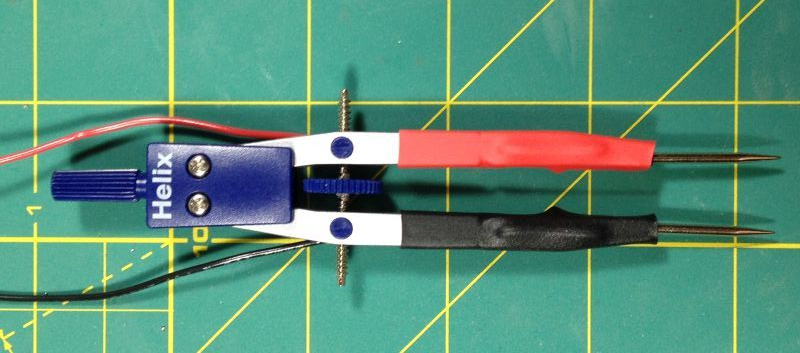
That is where the idea behind “Multimeter Probe Goes Full Circle” becomes delightfully clever. Instead of buying an expensive adjustable probe, one maker-style solution turns a drafting compassthe old-school circle-drawing tool from geometry classinto a variable-spacing multimeter probe. The result is a low-cost, adjustable, surprisingly practical test accessory for electronics troubleshooting, especially when working around small components.
It is the kind of hack that makes you stare at a pencil compass and think, “You were pretending to be a math tool this whole time, weren’t you?”
What Does “Multimeter Probe Goes Full Circle” Mean?
The title is a playful nod to the drafting compass. A compass normally draws circles by holding one point steady while the other leg sweeps around with a pencil. In this project, that same adjustable geometry becomes useful for electrical testing. Replace the pencil side with a second metal point, add wires, connect the tips to a multimeter, and suddenly the circle-making tool becomes a dual-point electrical probe.
The key advantage is adjustable spacing. With ordinary multimeter probes, your hands must hold two separate leads at exactly the right distance. On small surface-mount components, that gets awkward fast. One tiny hand tremor and the probe slips, bridges two pads, or performs a dramatic launch into the carpet. The compass-style probe keeps the two tips set at a fixed distance, so you can place both points onto a component or test pads with better control.
This idea is especially useful for checking SMD resistors, capacitors, LEDs, jumpers, fuses, and circuit board traces. It can also help when comparing repeated measurements across identical pad spacing. You adjust once, test many times, and avoid the finger gymnastics normally required by two independent probes.
Why Standard Multimeter Probes Struggle With Tiny Electronics
A standard multimeter probe is designed to be general-purpose. That is both its strength and its weakness. It can touch a battery terminal, appliance connector, automotive fuse, wire end, or breadboard rail without much trouble. But modern electronics often use surface-mount devices that are only a few millimeters wide.
When the target is small, several problems appear:
- Probe tips are too large: A chunky tip can touch two pads at once and create a false reading.
- Both hands are occupied: Holding two probes leaves no hand free to adjust the circuit, press a button, or stop a board from sliding away like a scared crab.
- Tip spacing is inconsistent: Repeated measurements become slower because the user must re-aim both probes every time.
- Pressure varies: Uneven pressure can affect resistance readings or cause intermittent contact.
- Short-circuit risk increases: On live low-voltage electronics, slipping across adjacent pins can cause troubleshooting to become “new problem creation.”
Professional labs solve this with specialty accessories: tweezer probes, SMD probe clips, spring-loaded pogo pins, micro hooks, Kelvin clips, fixture probes, and premium test lead kits. These tools are excellent, but not every hobbyist wants to pay premium prices for an accessory used occasionally. The compass probe sits in the sweet spot between “useful” and “I can build that before my coffee gets cold.”
How a Compass Becomes an Adjustable Multimeter Probe
The basic concept is simple. A drafting compass already has two arms that can be adjusted to a chosen distance. In its original job, one arm has a sharp point and the other holds a pencil. For a probe, both arms need conductive points. A maker can use spare compass needles, steel pins, sewing needles, small probe tips, or better yet, spring-loaded pogo pins for gentler contact.
The Core Parts
A typical DIY adjustable multimeter probe may use:
- A metal or plastic drafting compass with a firm hinge
- Two sharp conductive tips or needle-style contacts
- Flexible insulated wire
- Banana plugs or leads compatible with a digital multimeter
- Heat-shrink tubing in red and black
- Epoxy, hot glue, or mechanical fasteners to stabilize loose joints
- Optional pogo pins for spring-loaded contact
The compass hinge sets the distance between the two tips. The wires connect each tip to the multimeter inputs. Red and black insulation helps identify polarity, though resistance and continuity measurements do not usually care which direction the probes are connected. It also makes the tool look less like it escaped from a middle-school geometry drawer.
The Most Important Mechanical Detail
The probe only works well if the arms stay where you put them. A sloppy hinge defeats the purpose. The point of the project is repeatable spacing, so the compass should have a thumbwheel, screw adjustment, or enough friction to hold position. If the arms wander during measurement, you are back to the original problem, except now with extra metal parts.
Many compass-style probes benefit from immobilizing secondary joints. Some drafting compasses have knees or adjustable sections that are helpful for drawing but annoying for testing. Locking those joints with adhesive or a small fastener can make the tool much more stable. A rigid frame gives the tips predictable geometry, which is the whole party trick.
Where This Probe Shines
A circular-origin multimeter probe is not a universal replacement for quality test leads. It is a specialty tool, and specialty tools are happiest when they are not asked to do everything. Used in the right situation, though, it can be wonderfully efficient.
Testing SMD Resistors and Capacitors
For surface-mount resistors, the adjustable spacing can be set to match the component length. Then both tips land on opposite ends with one controlled motion. This is faster than chasing each side with separate probes. It can also reduce mistakes when sorting loose SMD parts, verifying values, or checking whether a component is still connected in circuit.
Capacitors can be trickier because in-circuit readings may be influenced by surrounding components, but the probe still helps with physical access. For quick comparison checks, continuity tests, or identifying shorts across rails, it can save time.
Checking Continuity Across PCB Pads
Continuity testing is one of the most satisfying uses of a digital multimeter. Touch two points, hear a beep, feel like a wizard. The compass probe improves this by making it easier to test pad pairs that share common spacing. It is useful for headers, jumpers, small fuses, test pads, solder bridges, and repair work after reflow.
Finding Shorts on Low-Voltage Boards
When a board refuses to power up, checking for shorts between power and ground is often one of the first steps. An adjustable dual-tip probe can make this faster on boards with repeated capacitor footprints or dense power filtering sections. Set the spacing, touch across each part, and listen for continuity. If the meter screams at you, congratulations: you have found either a clue or a new reason to sigh.
Working With Repeated Pad Spacing
The probe is handy when a board has repeated geometry: rows of passives, connector pins, programming pads, LED pads, and small test points. Repeatable spacing means fewer hand adjustments and more consistent contact.
Where It Does Not Belong
This point deserves its own section because electricity has no sense of humor. A DIY compass probe should be treated as a low-voltage electronics bench tool, not a mains-voltage accessory. Do not use homemade needle probes on wall outlets, breaker panels, HVAC equipment, industrial controls, electric vehicle systems, solar strings, or any high-energy circuit.
For mains and high-energy work, use commercially rated test leads and probes that match the correct measurement category, voltage rating, and current rating. CAT ratings matter because they address transient energy risk, not just the steady voltage printed on a label. A probe that seems fine on a small DC circuit may be completely inappropriate in a CAT III or CAT IV environment.
A safe rule is simple: if the circuit can injure you, start a fire, arc violently, or destroy the meter, do not improvise. Use proper equipment, follow the meter manual, inspect the leads, keep fingers behind probe guards, and de-energize circuits whenever possible. The compass probe is for delicate electronics troubleshooting, not proving your bravery to the power grid.
Design Improvements Worth Considering
The basic compass probe is clever, but it can be improved. Makers rarely stop at “good enough.” That phrase usually lasts about twelve minutes before someone adds magnets, LEDs, or a 3D-printed enclosure shaped like a cyberpunk beetle.
Use Pogo Pins Instead of Fixed Needles
Pogo pins are spring-loaded contacts used in test fixtures and programming jigs. They apply gentle pressure and compensate for small height differences. In a compass probe, pogo pins can make contact smoother and reduce scratching on pads. They are especially useful for gold-plated test pads or boards you do not want to stab like a tiny vampire hunter.
Add Better Strain Relief
Wires connected directly to moving arms can break after repeated use. Heat-shrink tubing, small cable ties, flexible silicone wire, and adhesive anchors can protect solder joints. Good strain relief turns a quick hack into a tool that survives more than one debugging session.
Insulate Everything Except the Tips
Exposed metal should be minimized. Heat shrink can cover the arms, solder joints, and wire exits. Only the actual contact tips need to remain exposed. This reduces accidental shorts and makes the probe more comfortable to handle.
Add a Spacing Scale
A small printed or engraved scale can help repeat common spacing. For example, a user might mark settings for common SMD sizes or header spacing. It does not need laboratory-grade precision to be useful. Even rough reference marks can speed up setup.
Build a 3D-Printed Handle
A custom handle can make the probe easier to grip and safer to use. It can also hold the wires neatly and prevent the compass arms from twisting. If the project becomes part of a daily bench setup, ergonomics matter. A tool that feels good in the hand gets used; a tool that pokes your palm gets thrown into the drawer of shame.
How It Compares With SMD Tweezer Probes
SMD tweezer probes are probably the closest commercial alternative. They look like tweezers with electrical contacts at the tips. Some connect to a standard multimeter, while others are built into dedicated LCR meters for measuring resistance, capacitance, and inductance.
Tweezers are fast for grabbing small components. They feel natural for loose SMD parts and two-terminal devices. However, they rely on hand pressure, and the tip spacing changes as you squeeze. The compass-style probe is different: it holds a set spacing. That makes it useful when you want consistent geometry rather than a pinching action.
In simple terms, tweezer probes are better for grabbing parts; compass probes are better for landing on repeated fixed points. A well-equipped bench can benefit from both. A budget bench can start with whichever one solves the most annoying problem today.
Accuracy: What the Probe Can and Cannot Improve
An adjustable probe improves access and repeatability, but it does not magically upgrade the accuracy of the multimeter. Measurement quality still depends on the meter, the test mode, the circuit condition, the contact resistance, and the lead quality.
For voltage checks on low-voltage electronics, the probe can be excellent because it helps maintain stable contact. For resistance measurements, remember that in-circuit readings may include parallel paths. A resistor measured on the board might read lower than expected because other components are connected around it. That is not the probe lying; that is the circuit being sociable.
For very low resistance measurements, ordinary two-wire probes have limitations because lead and contact resistance become significant. High-precision work may require four-wire Kelvin measurement. The compass probe is best viewed as a convenience tool for practical debugging, not a calibration instrument.
Practical Safety Checklist
Before using any multimeter probe, homemade or commercial, run through a quick safety check:
- Use the compass probe only on low-voltage electronics.
- Inspect wires for cuts, loose solder joints, or exposed conductors.
- Confirm the multimeter is set to the correct mode before touching the circuit.
- Do not measure current unless the tool and wiring are specifically designed for it.
- Keep exposed metal tips as short as practical.
- Use insulated wire and secure strain relief.
- Never use DIY probes on mains or high-energy circuits.
- When in doubt, stop and use properly rated commercial test leads.
The best bench tools make work easier without making it riskier. That is the standard this project should meet.
Why Makers Love This Kind of Tool Hack
The charm of the compass multimeter probe is not just that it works. It is that it reframes an ordinary object. A drafting compass already solves a mechanical problem: keeping two points separated by an adjustable distance. Electronics testing sometimes needs exactly that. The hack is less about inventing from nothing and more about noticing that one tool has been quietly auditioning for another job.
This is classic maker thinking. Look at the problem, look at the junk drawer, then introduce them to each other. Sometimes the result is ugly. Sometimes it is brilliant. Sometimes it is both, which is honestly the sweet spot.
Hands-On Experience: What It Feels Like to Use a Compass-Style Probe
The first time you use an adjustable compass-style multimeter probe, it feels slightly strange. Your hands expect two floppy leads, but instead you have one rigid tool with two points moving together. After a few measurements, the advantage becomes obvious. The motion is calmer. You are not chasing the second pad while the first probe slips away. You are placing a small bridge across two targets, and the meter responds.
On a crowded PCB, that difference matters. Imagine checking a row of tiny resistors near a microcontroller. With standard probes, you must steady the board, aim the black lead, aim the red lead, avoid the nearby capacitor, avoid the IC pins, read the display, then repeat. It works, but it feels like playing Operation after drinking espresso. With the adjustable probe, you set the spacing once and move down the row more confidently.
The experience is especially pleasant in continuity mode. The audible beep lets you keep your eyes on the probe tips instead of the display. You can check solder joints, jumper pads, and trace connections quickly. When the spacing is right, the tool feels like a small measuring caliper that happens to speak fluent electricity.
There are quirks. Sharp needles can scratch pads if you press too hard. A cheap compass may flex. Wires can tug at the arms if they are too stiff. The hinge may loosen after repeated use. These are not deal-breakers, but they teach an important lesson: the electrical idea is simple, while the mechanical quality determines whether the tool becomes useful or annoying.
A better build uses flexible silicone wire, strong strain relief, and short exposed tips. Pogo pins make the tool feel more refined because the spring action absorbs small changes in board height. Heat shrink improves grip and reduces accidental contact. A thumbwheel adjustment is much better than a loose friction hinge because it holds spacing more reliably.
The most memorable benefit is reduced frustration. Debugging electronics is often a battle against uncertainty. Is the resistor wrong? Is the pad cracked? Is the trace open? Is the meter lead slipping? A stable probe removes one variable from the mess. That alone can make a troubleshooting session feel less like detective work performed during an earthquake.
For beginners, building the probe is also educational. It teaches continuity, polarity, insulation, contact resistance, strain relief, and the importance of using the right tool for the right voltage. For experienced makers, it is a reminder that useful bench upgrades do not always need firmware, Bluetooth, or an app. Sometimes they need a compass, two wires, and the willingness to look mildly ridiculous for ten minutes.
Would this replace a professional SMD tweezer meter or a high-quality probe kit? No. But that is not the point. It fills a specific gap: repeatable, adjustable, low-voltage probing on small electronics. It is cheap, understandable, repairable, and easy to customize. In a world where many tools arrive sealed, branded, and expensive, there is something deeply satisfying about making a useful probe from an object that once drew circles on notebook paper.
Conclusion
Multimeter Probe Goes Full Circle is more than a clever title. It is a perfect example of practical creativity in electronics. By turning a drafting compass into an adjustable multimeter probe, makers can solve a real bench problem: testing small, closely spaced components without juggling two independent leads.
The design is simple, affordable, and surprisingly effective for low-voltage electronics work. It helps with SMD components, PCB continuity checks, repeated pad spacing, and quick troubleshooting. It also invites improvement through pogo pins, insulation, better wiring, strain relief, and custom handles.
Still, safety must remain the bright red line. Homemade probes belong on low-energy circuits, not mains wiring or high-voltage systems. For dangerous environments, use properly rated commercial equipment and follow professional safety practices.
In the end, this project proves that a good tool hack does not need to be complicated. Sometimes the best idea is already sitting in a drawer, waiting to go full circle.
Note: This article is written for educational and editorial purposes. DIY multimeter accessories should only be used on low-voltage electronics unless they are properly engineered, tested, and rated for the intended environment.